LaserMaker 2.3.2 Update Details
Preface
LaserMaker 2.3.2 introduces targeted optimizations and fixes to enhance your laser processing workflow. This document outlines key updates designed to improve stability and user experience. Let’s dive into the details.
1. Download Channel
You can find LaserMaker 2.3.2 on our official website and download it for use.
https://www.thunderlaser.com/downloads/
2. Optimizations & New Features
2.1 Multi-Mark Point Support
Added support for multiple even-numbered Mark points (recommended: 4 Mark points). Compared to 2 Mark points, multiple Mark points enable automatic scaling to reduce sample errors caused by printers:
- Precision with 2 Mark points: ≤ 0.5mm
- Precision with 4 Mark points: ≤ 0.25mm
2.2 Halftone Mode for Image Processing
Added Halftone Mode in image adjustment (differs from Dot Matrix Mode: Halftone Mode produces circular dots):
- DPI: Number of pixels per inch, where a higher value means finer dot details and a lower value results in coarser dots.
- LPI: Number of lines per inch, with a higher value bringing denser dots and sharper clarity, while a lower value leads to a blurrier effect.
- Angle: The angle of the dot matrix lines.

2.3 Dot Matrix Mode Naming Update
In Image Processing >> Dot Matrix Mode, the "None" option is renamed to "Threshold", and imported canvas now uses Threshold processing by default.
2.4 Measurement Toolbox: Annotation Mode
Added Annotation Mode to the Measurement Toolbox (to fix measurement results on the canvas):
- After switching to Annotation Mode, left-click the canvas to fix the measurement result at the clicked position.
- Difference between Measure and Annotate:
- Measure: Left-click to dismiss the result.
- Annotate: Left-click to fix the result (results are saved in a new layer).
2.5 UI Interaction Optimization for Coordinate Addition (Top Camera Calibration)
Updated coordinate addition/editing for camera calibration with 5 key improvements:
- "Add" & "Edit" Modes:
- "Add" Mode: Once selected, the icon remains active. Double-click to add coordinates — the newly added coordinate will display in green, while existing ones will show in red.
- "Edit" Mode: Supports modifying all coordinates. Only the selected coordinate will be displayed in green, and the rest will show in red.
- "Photo" Auto-Triggers Add Mode: Clicking "Photo" activates Add Mode automatically.
- Double-Click to Modify Coordinates:
- Double-click within 70 pixels of Coordinate 1: Add new Coordinate 1.
- Double-click beyond 10 pixels of Coordinate 1: Add Coordinate 2.
- For existing coordinates (1, 2, 3...), double-click within 10 pixels of Coordinate 1: Modify Coordinate 1 (does not affect the order of new coordinates).
- Deletion Restriction: Only the most recently added coordinate can be deleted. If you attempt to delete a non-latest coordinate, a pop-up will appear with the prompt: "Deletion failed! Only the last added coordinate can be deleted."
- Updated Right-Side Instructions:
a. Please zoom and pan the photo to locate the centre of each cross; be sure to add exactly 99 coordinates in left-to-right order!
b. When the "Add" icon is selected, each double-click with the left mouse button adds a coordinate. However, double-clicking near an existing coordinate is treated as modifying its position, and no new coordinate will be added.
c. When the "Edit" icon is selected, you can modify the position of a coordinate by clicking and dragging it with the left mouse button.
d. Clicking the "Delete" icon removes the last added coordinate.
2.6 Manual Camera Selection for Live Preview
Added "Camera - LiveView" in Settings >> Camera (to select the camera used for live preview).
2.7 "Line Change Delay" & "X Unidirectional Scan Buffer Length."
Added 2 parameters in Vendor Setting >> Processing:
- Line Change Delay: Dwell time of the Y-axis after finishing one engraving line, before moving to the next line
- X Unidirectional Scan Buffer Length: For left-to-right engraving, the buffer distance is added only to the left (adjusted based on scan direction)
2.8 Support for Gradient Power in Bidirectional Engraving Parameters
Added support for setting the minimum and maximum power during engraving calibration, with the following rules:
- If only one test speed is selected, Processing will use the default power.
- If multiple test speeds are selected: Gradient power effect will be applied across different speeds (e.g., default power = 20, max power = 50; test speeds = 500, 600, 700 → power for 500 = 20, 600 = 35, 700 = 50).
- UI Behavior: The "Max Power" option is highlighted in blue only when multiple speeds are selected; it is grayed out when a single speed is selected, or no speeds are selected.
2.9 Optimize the focal length setting for auto-focus on the dual source controller
Added support for selecting different lens barrels on the device panel, enabling compatibility with corresponding focal lengths for each lens barrel:
2.9.1 For Single Source Devices (Identified by Laser Type in Vendor Settings)
- If the source is CO2 (RF Tube/Glass Tube): Only "CO2 (1.5/2/2.5/4" Lens)" and "CO2 Custom" are displayed. During processing, select the focal length corresponding to the actual lens barrel used.
- If the source is Fiber, only "Fiber Custom" is displayed.
2.9.2 For Dual Source Devices
The software displays 5 editable focal length options:
- Dual Source - CO2 (3" Lens)
- Dual Source - Fiber (3" Lens)
- CO2 (1.5/2/2.5/4" Lens)
- CO2 Custom
- Fiber Custom
- During processing, select the focal length corresponding to the actual lens barrel used (CO2 & Fiber options correspond to dual source lens barrels).
2.10 Support for Engraving Acceleration Setting
Added an "Engraving" section in Vendor Settings to configure engraving acceleration:
- Input range: 0–100,000 mm/s² (maximum 100,000 mm/s²)
- Note: This is a factory default setting (generally not required to be modified), designed to adapt to Titan series parameter configurations (segmented acceleration: 500 mm/s - 3G, 2000 mm/s - 5G, 3000 mm/s - 8G).
2.11 Support for 5 Decimal Places in Step Length
Step length-related values now support up to 5 decimal places for higher precision.
2.12 Optimization of Laser Power Parameter Input
In Vendor Settings >>Laser compensate>> Laser Power, the original drop-down selection menu is replaced with a direct input box:
- Input range: 10–300W (supports custom power values within this range).
2.13 Support for Backlash Compensation Optimization
Enabling this function can reduce the misalignment issue where the start point and end point of the cut graphic fail to coincide.
2.14 UI Optimization for Vendor Settings
The UI of the Vendor Settings page has been adjusted as follows:
- The color of the top toggle buttons is updated to match the theme color (paired with white) for clearer interactive feedback.
- The dark background color of the original parameter table is replaced with a lighter shade (as shown in the attached reference image).
2.15 Optimization of User/Vendor Parameter Import/Export
Enhanced flexibility and security for parameter import/export:
- Users can now select specific parameters to export (all parameters are selected by default, and only the checked items will be exported).
- If the imported file contains Vendor Parameters, the Vendor Settings must be unlocked first to complete the import successfully.
- The "Export" button will be grayed out if no parameters are selected.
2.16 Optimization of Material Test Matrix
Enhanced features for the Material Test Matrix:
- New "Preset Matrix" Function (with Save/Delete Support)
- The software uses a default matrix upon initial download. Click "Save" to open a pop-up for naming the preset, then save all current matrix settings to the "Preset Matrix" list.
- Switch between saved presets via the drop-down menu (all settings will be replaced with those of the selected preset).
- Click "Delete" to remove the currently selected preset.The "Delete" button is grayed out if the default matrix is selected.
- Import/Export Support
- Export all current matrix parameters as a file, which can be imported for use on the same or other computers.
- Added "DPI" Test Parameter (for Engraving Process)
- When the processing technique is set to "Engraving", the "DPI" parameter is now available in the test settings.
- Persistent Parameter Retention
- Each time the matrix is opened, it loads the parameters configured in the last session.
- "Reset Matrix" Function
- Click to clear all settings made since the Material Test Matrix was opened (restores the initial state).
2.17 Optimization of DPI Parameter Input
Changed the DPI input method from a drop-down selection menu to a direct input box, with a maximum supported value of 2540 DPI.
2.18 Optimization of Rotary Setup Wizard
Added options for chuck-type rotary axis and roller-type rotary axis, along with corresponding schematic diagrams to assist with configuration.
2.19 Expanded Rotary Axis Diameter Range
Increased the input range for the rotary axis diameter to 0–1000 mm (supports larger workpiece sizes).
2.20 Layout Optimization of the Movement Panel
Redesigned the panel layout from vertical (top-bottom) to horizontal (left-right) for more intuitive operation.
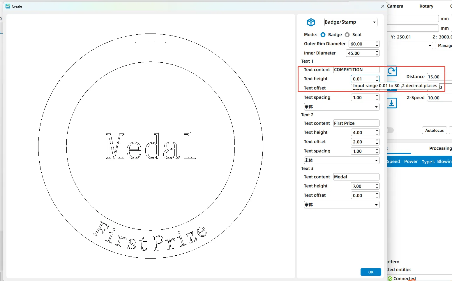
2.21 Adjustment of Text Height Input for Badge/Stamp
Updated the text height input range for badge/stamp in the creation module:
- Original range: 4–30 mm.
- New range: 0.01–30 mm (supports 2 decimal places for higher precision).
Updated the text height input range for badge/stamp in the creation module:
- Original range: 4–30 mm.
- New range: 0.01–30 mm (supports 2 decimal places for higher precision).
Still need help?
For specific technical questions or help requests, please open a Ticket with picture or video, so our Support team can assist you ASAP.
For the information provided in the ticket, please refer to this link:
Help Tech Support Troubleshoot Faster
End.
Related Articles
Manuals for LaserMaker Software
LaserMaker User's Manual Please see attached ENDTroubleshooting Guide for LaserMaker 2.0 License Key Activation Failure
Preface This guide helps resolve license activation failures in LaserMaker 2.0. For persistent problems, contact support with your version and error details. Phenomenon When attempting to activate LaserMaker using the license key, a "License ...Introduction to the Precise Preview Feature in LaserMaker
Preface In practical laser processing operations, if the full-frame preview accuracy of the equipment's top cover camera fails to meet precise positioning requirements, LaserMaker's "Precise Preview" feature provides a targeted optimization solution. ...Material Test Generator for LaserMaker
Preface: LaserMaker has a built-in test pattern generator to help you find the best processing parameter for your laser and any material you're working with. To open the Material Test Generator, go to the Laser Tools Menu and select Material Test. ...How to choose software after controller update
RDWorks for different controller Software Controller RDWorksV8.01.60 and older version RDC6442G-LY-B RDWorksV8.01.62 and latest version RDC6442G-LY-B AND RDC6442G-LY-1G A software installation package is in U-disk that came with the machine. If you ...