Replace the New Laser for TITAN
Preface
This document describes the approved procedure for replacing the RF (CO₂) Laser Source and Fiber Laser Source on TITAN (PRO) Series machines and for verifying laser beam centering and beam alignment after replacement.
Following these steps ensures safe replacement and proper beam alignment of the RF (CO2) laser source and the Fiber laser source.
Safety Information
⚠️ WARNING – LASER SAFETY
- Always wear laser safety goggles when firing or testing the laser.
- Never fire the laser with protective covers removed unless explicitly instructed.
- Ensure all safety interlocks are active, except when temporarily bypassed for alignment purposes only.
⚠️ ELECTRICAL SAFETY
- Always power off the machine and unplug the power cable before servicing.
- Never disconnect or reconnect cables while the machine is powered.
- Failure to follow these instructions may result in serious injury or equipment damage.
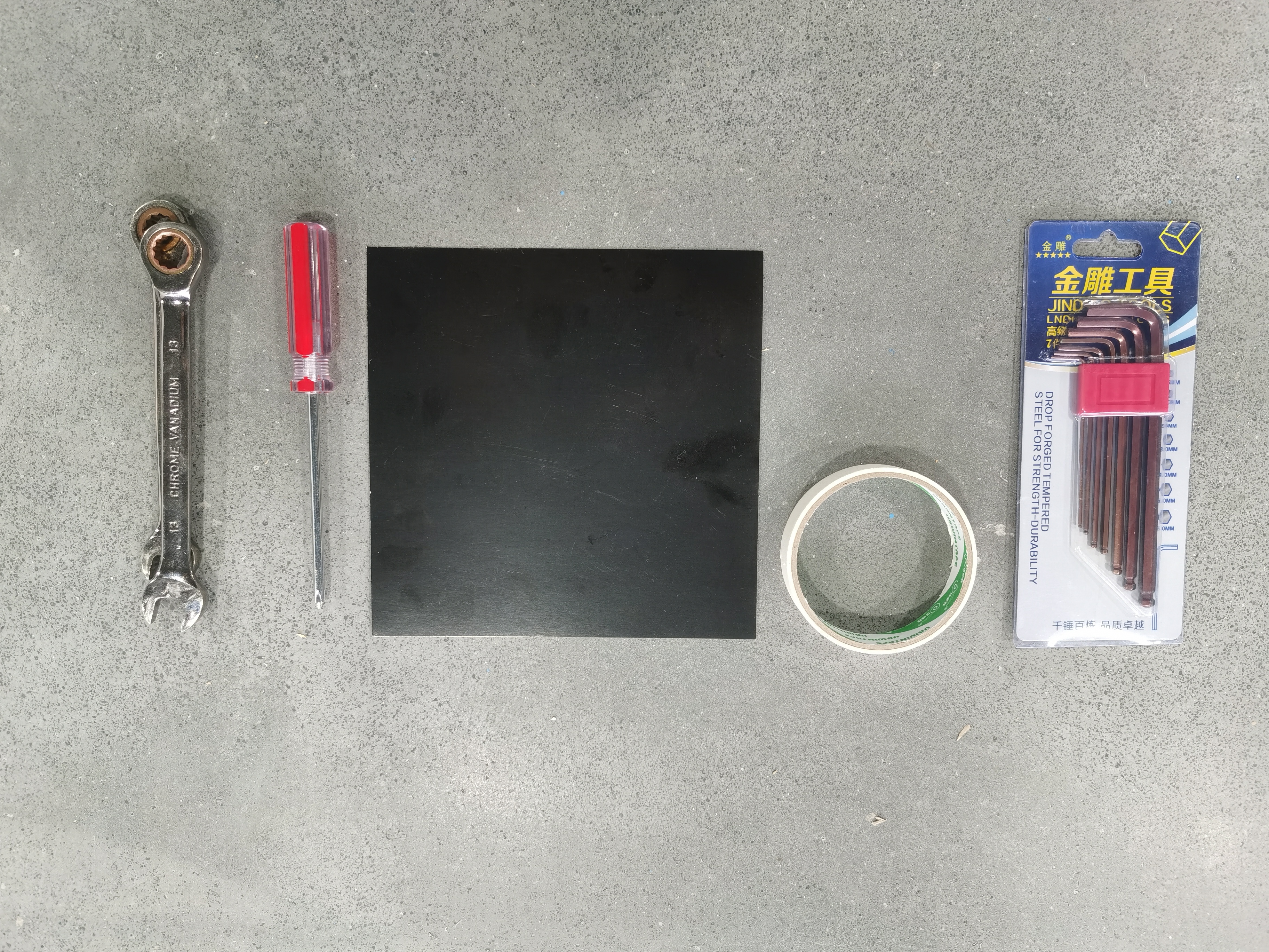
Tool Needed
Phillips screwdriver Double-sided Tape Hex Key Wrench Black Alignment Paper Open-End Wrench:13mm x2 |
|
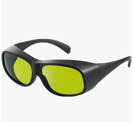
10.6 µm Laser Safety Goggle for CO2 laser 1064nm Laser Safety Goggle for fiber laser |
|
Replace the New Fiber Laser
1. Pre-Replacement Preparation
|
|
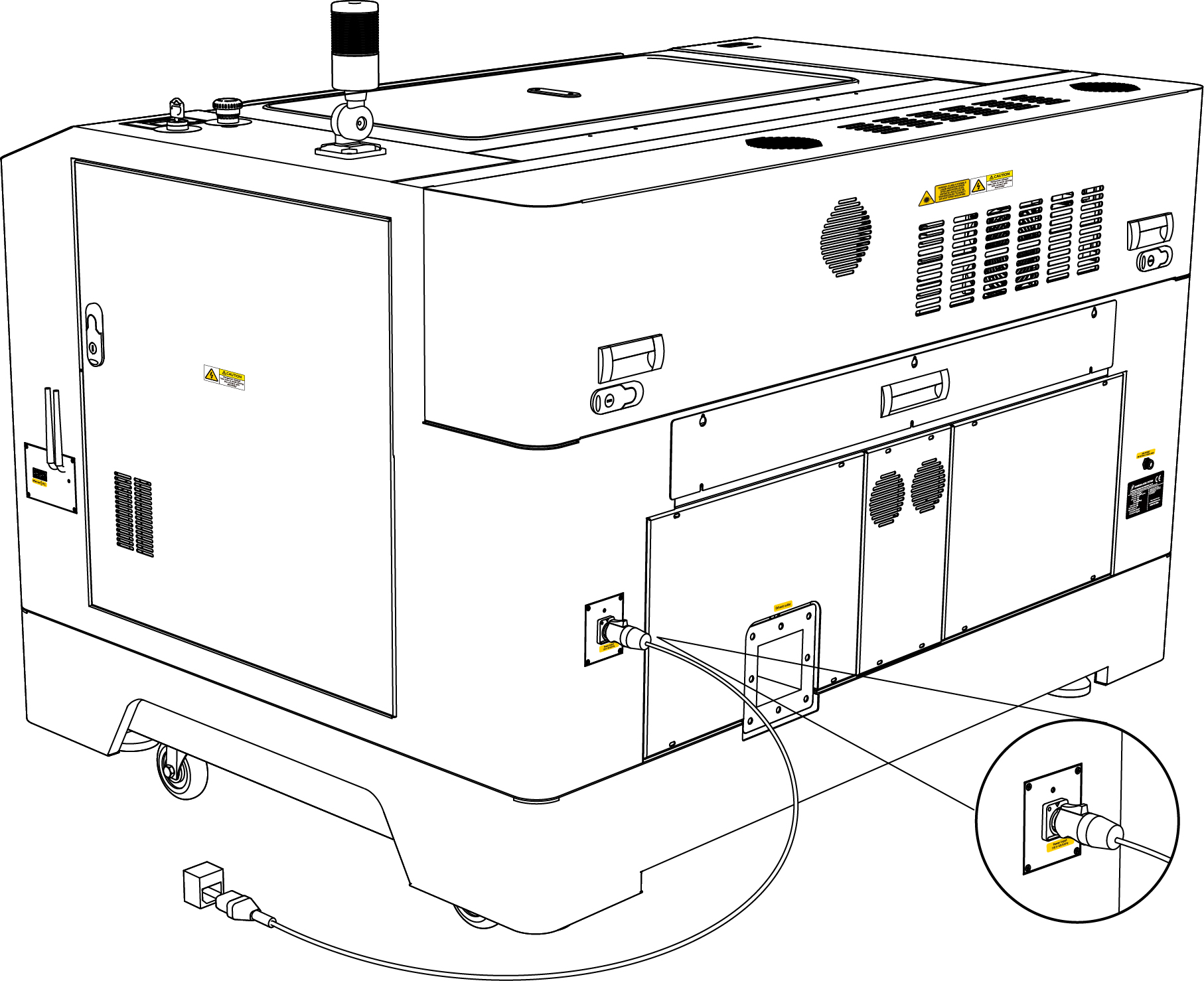
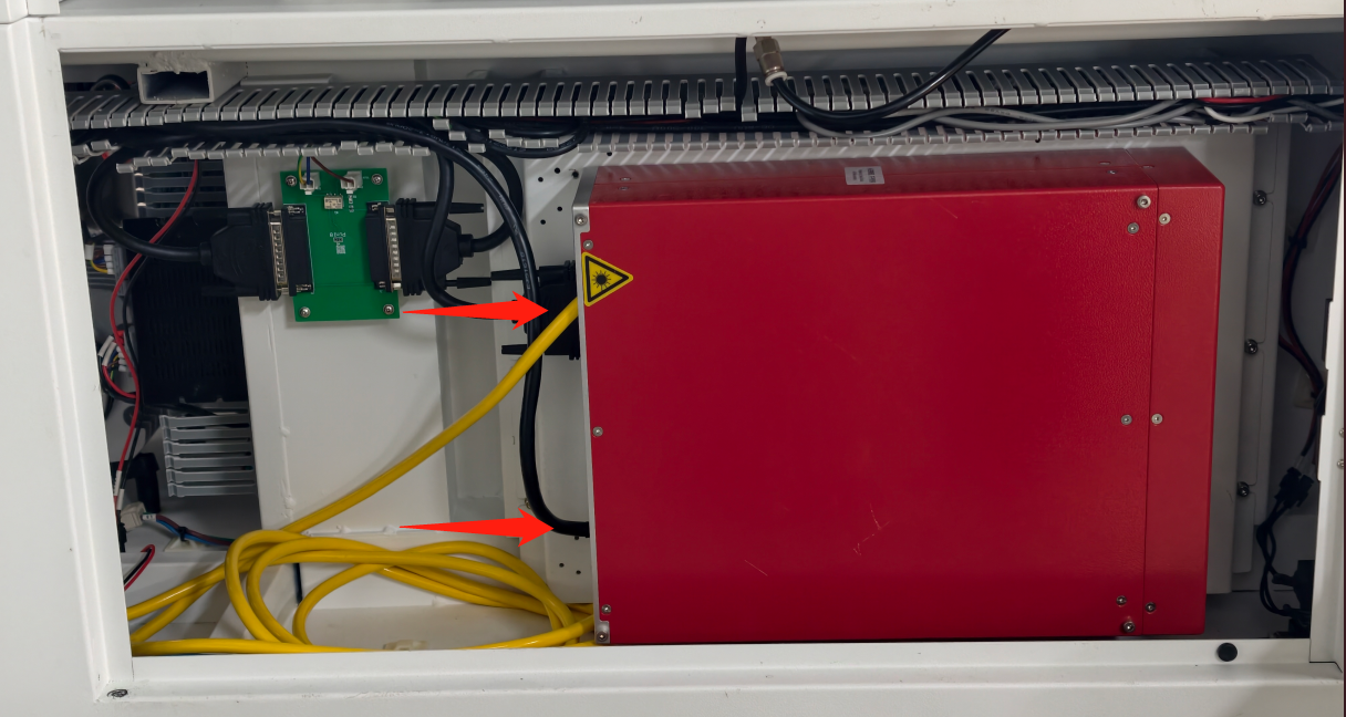
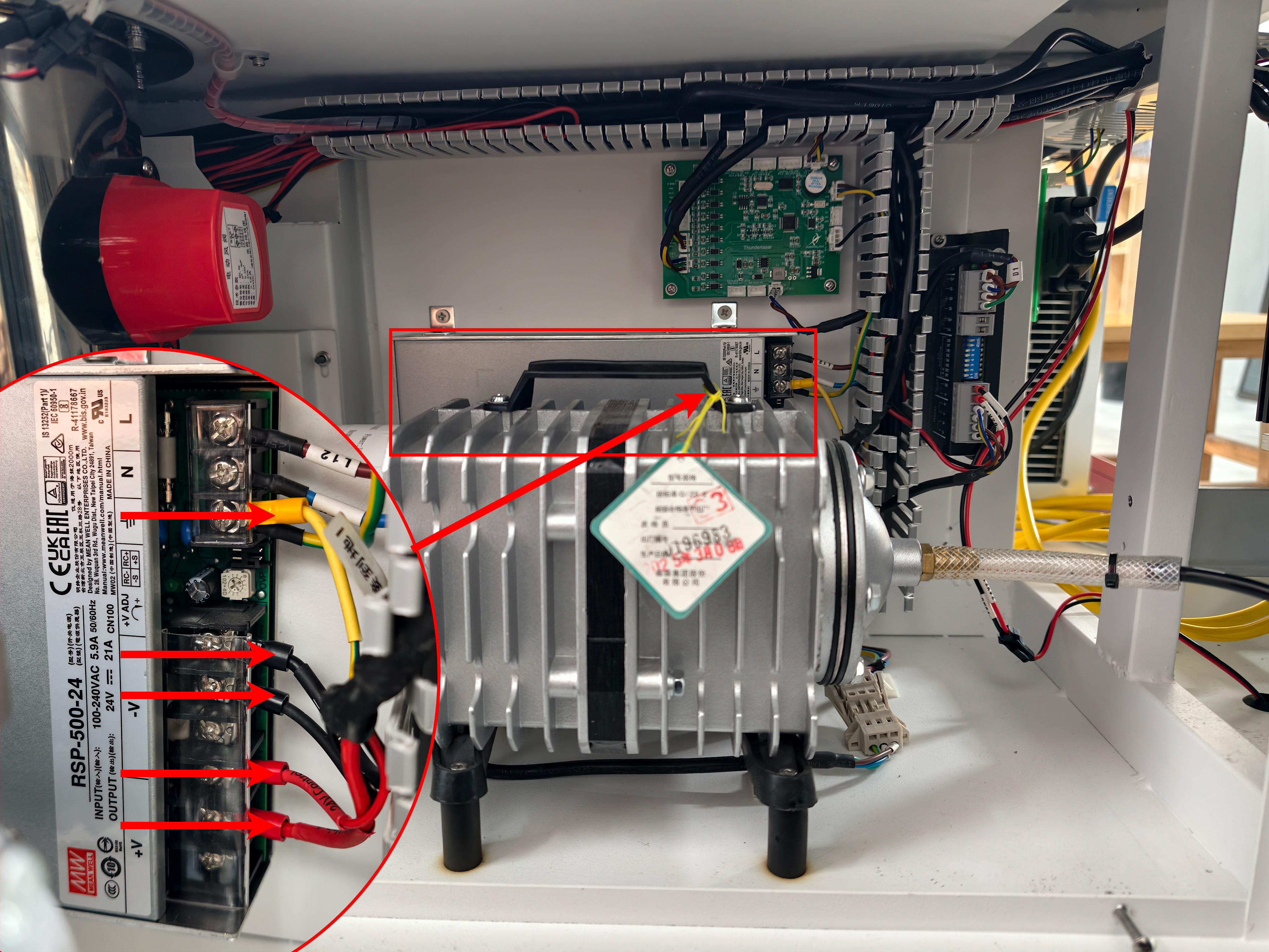
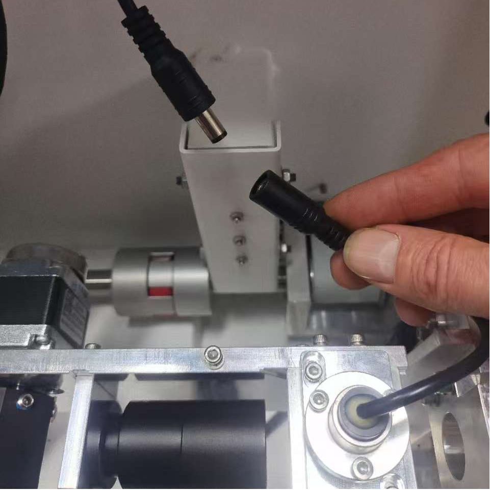
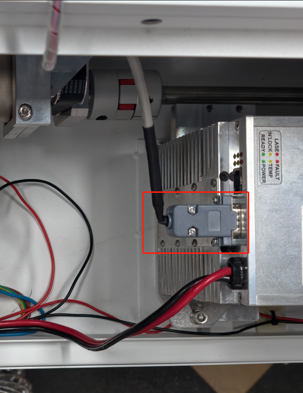
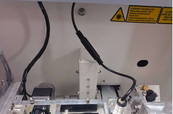
2. Electrical Disconnection
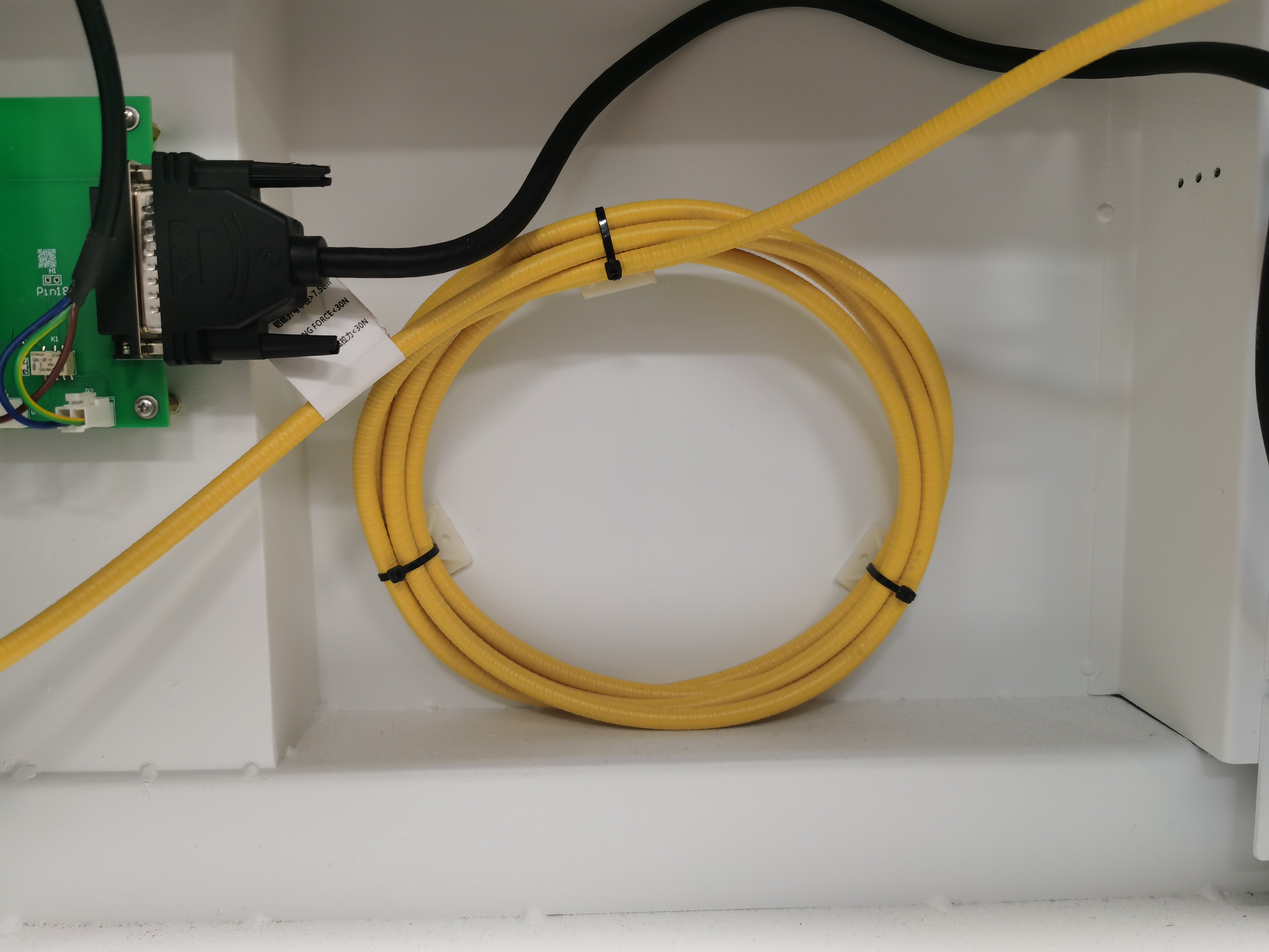
2.1. Remove the signal cable plug and the power cable of the fiber laser.
|
|
|
|
PRO TIP: Take a clear photograph of all cable connections before disassembly to assist with reinstallation.
3. Disassembly Procedure
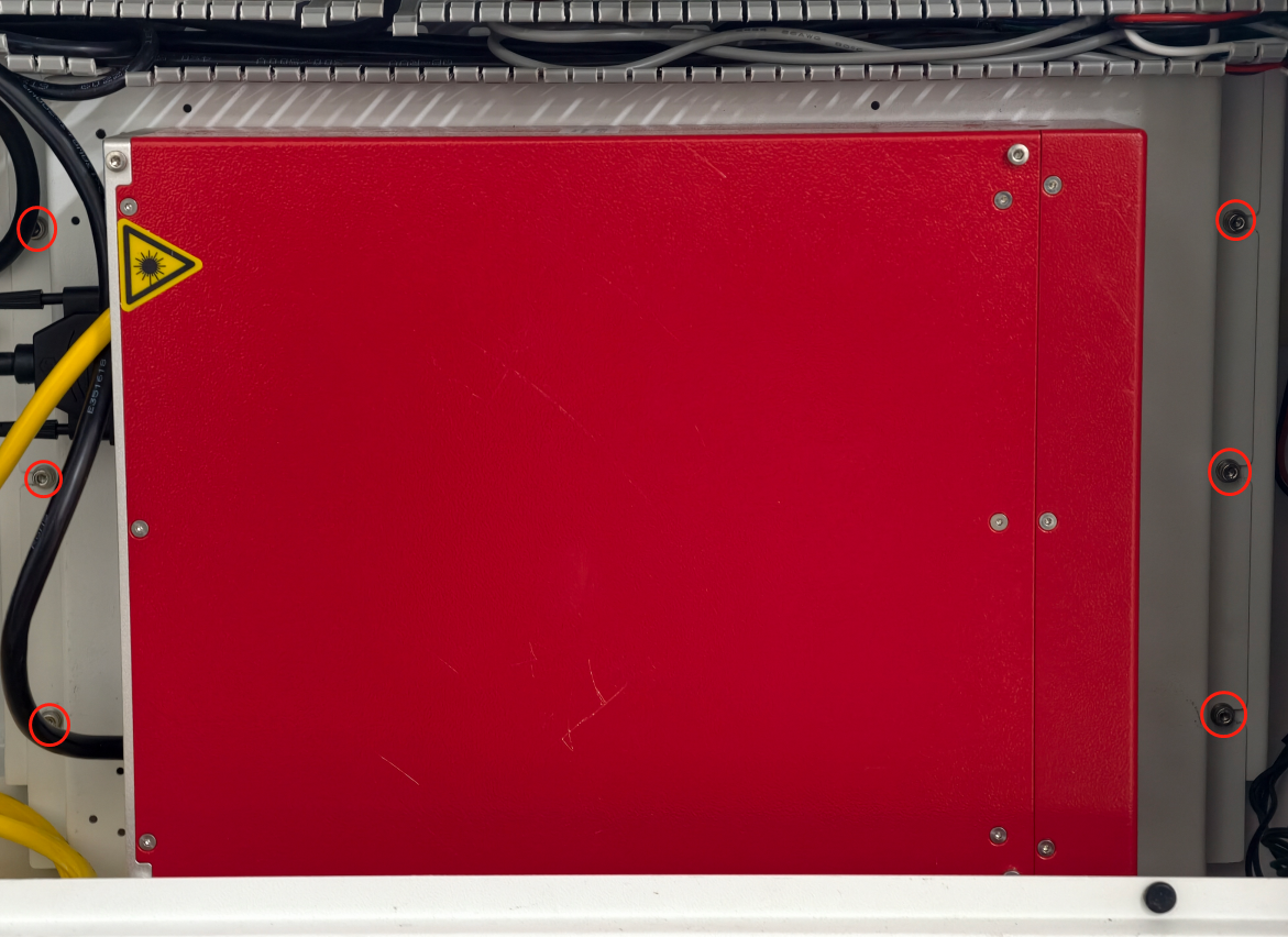
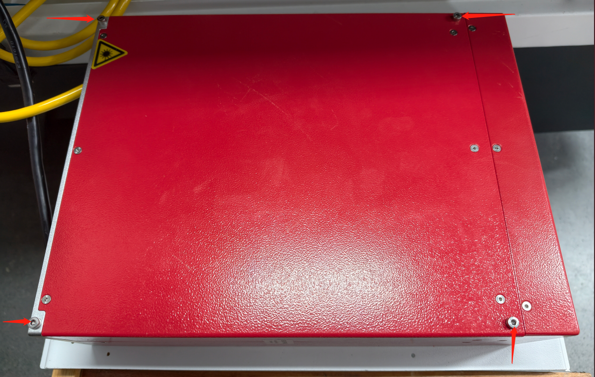
3.1. Removing the Shutter Cover
|
|
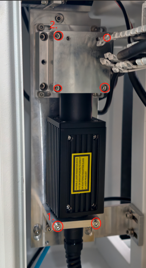
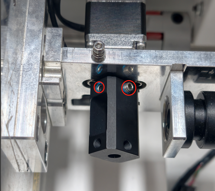
3.2. Old Fiber Laser Head Removal
NOTE: |
|
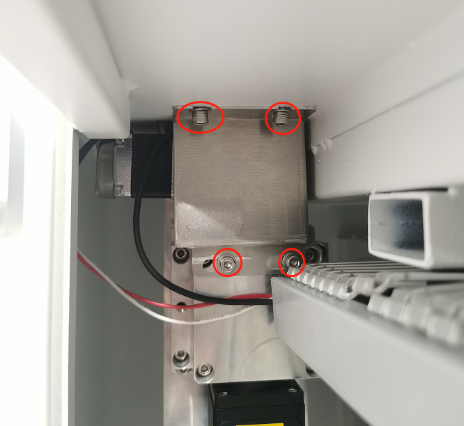
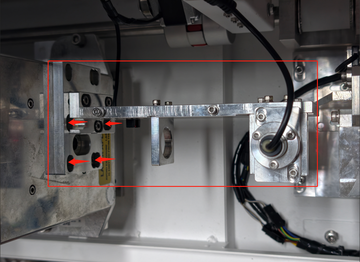
3.3. Old Fiber Laser Source Removal
|
|
|
|
4. Reassembly
|
|
WARNING⚠ Fiber Cable Handling The yellow fiber cable must never be bent at a 90° angle, as this may cause permanent damage.
|
|
5. Beam Inspection
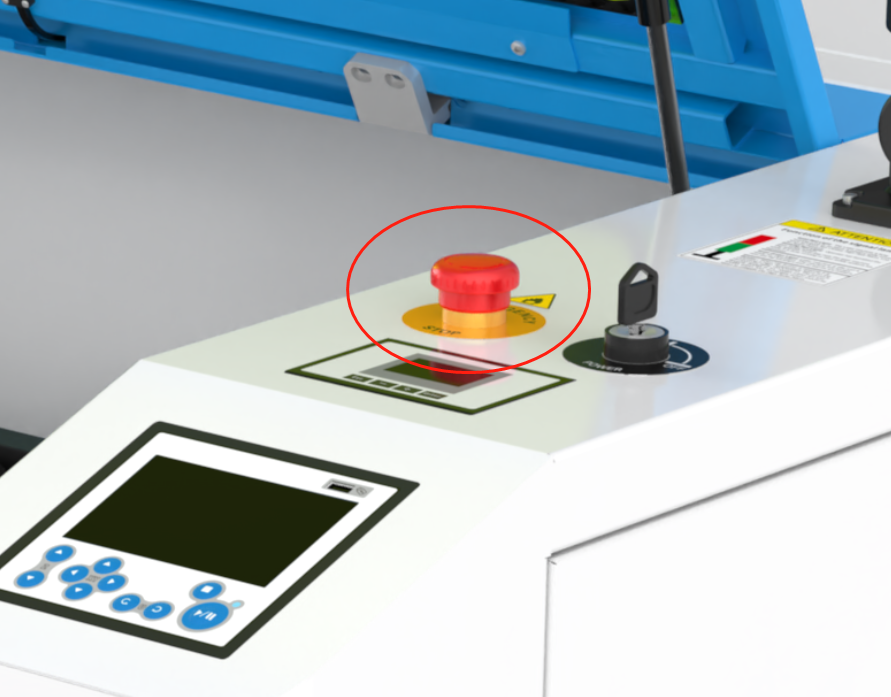
5.1. Bypass the Door Protection
|
|
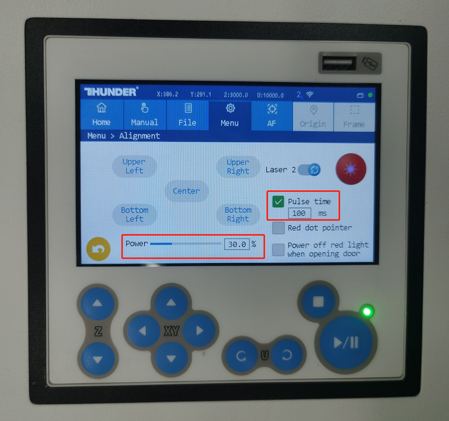
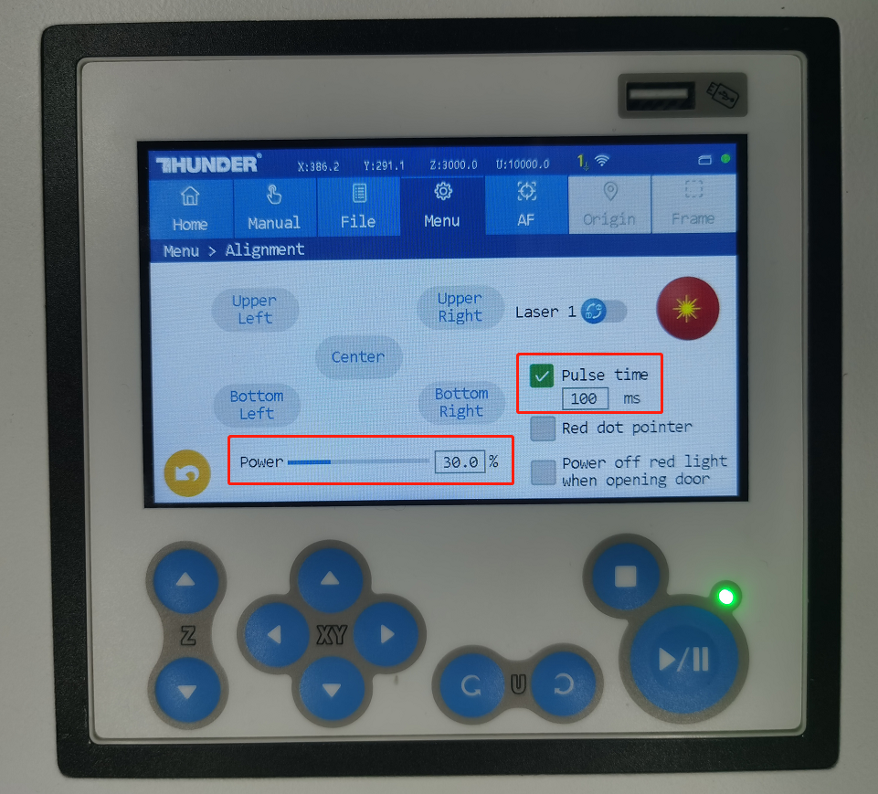
5.2. Configure Laser Parameters
|
|
5.3. Execute Test Pulse
|
|
|
|
6. Realignment After Replacing the Laser
After replacing the fiber laser, it is essential to verify the beam path alignment.
If the beam path is not correct, recalibrate it according to the beam alignment adjustment guide.
Reference:
Complete Guide To TITAN Series Laser Alignment
|
|
Replace the New RF Tube
1. Pre-Replacement Preparation
|
|
2. Optical Assembly Removal
2.1. Expander Holder Cover Removal
|
|
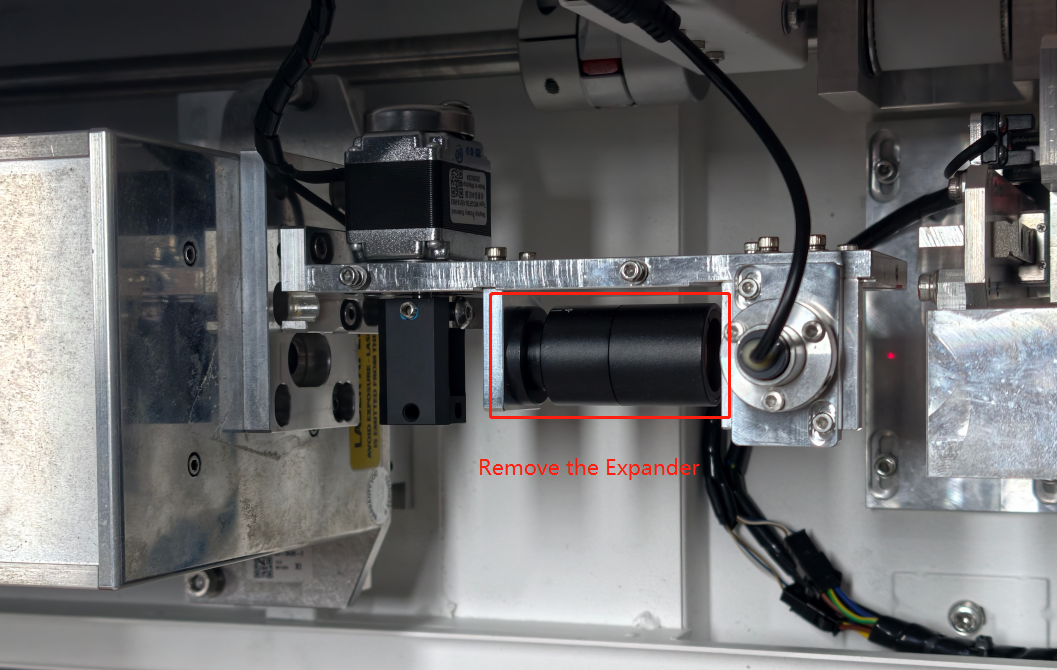
2.2. Expander Removal
|
|
2.3. The Shutter Blade Removal
|
|
2.4. Red Dot Pointer Cable Disconnection
|
|
2.5. Expander Holder Removal
|
|
3. Electrical Disconnection
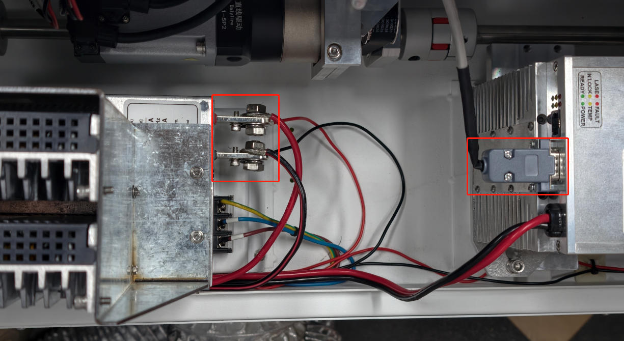
3.1. Remove the Signal Cable Plug and the Power Cable of the Laser.
PRO TIP: Take a clear photograph of all cable connections before disassembly to assist with reinstallation.
Signal Cable Removal
⚠ Do not twist, rock, or apply lateral force to avoid connector damage. |
|
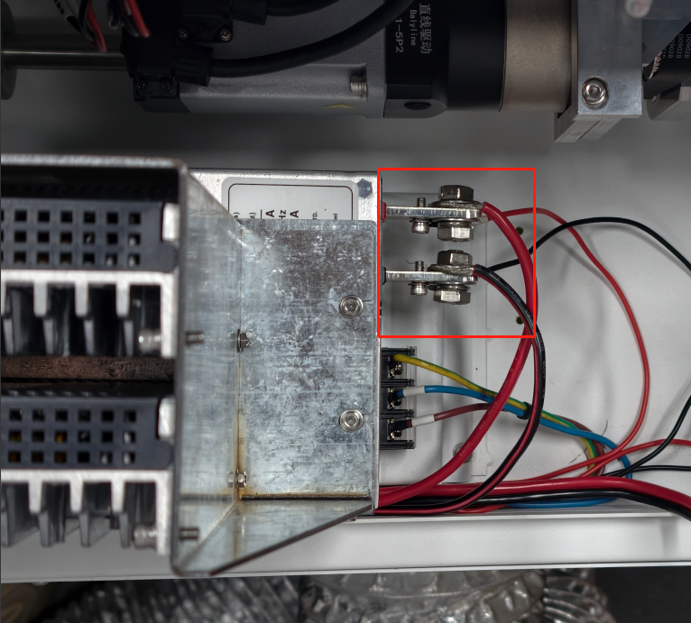
Power Cable Removal
|
|
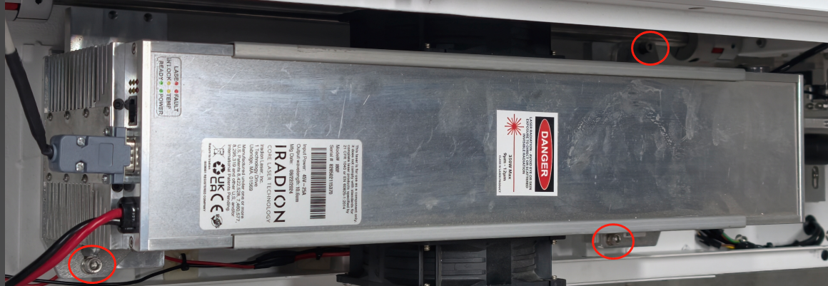
4. Old RF Laser Tube Removal
|
|
5. Reassembly
5.1. New Laser Source Mounting.
|
|
5.2. Expander Holder Reinstallation
⚠ CRITICAL: Reinstall the bracket WITHOUT any optical components installed (shutter blade, beam expander, motor).
|
|
5.3. Power Cable and Signal Cable Reconnection
|
|
5.4. Verify Holder Installation
WARRING:
Do NOT reinstall the shutter blade, beam expander, or shutter motor at this stage.
Direct access to the laser output is required for beam centering verification.
|
|
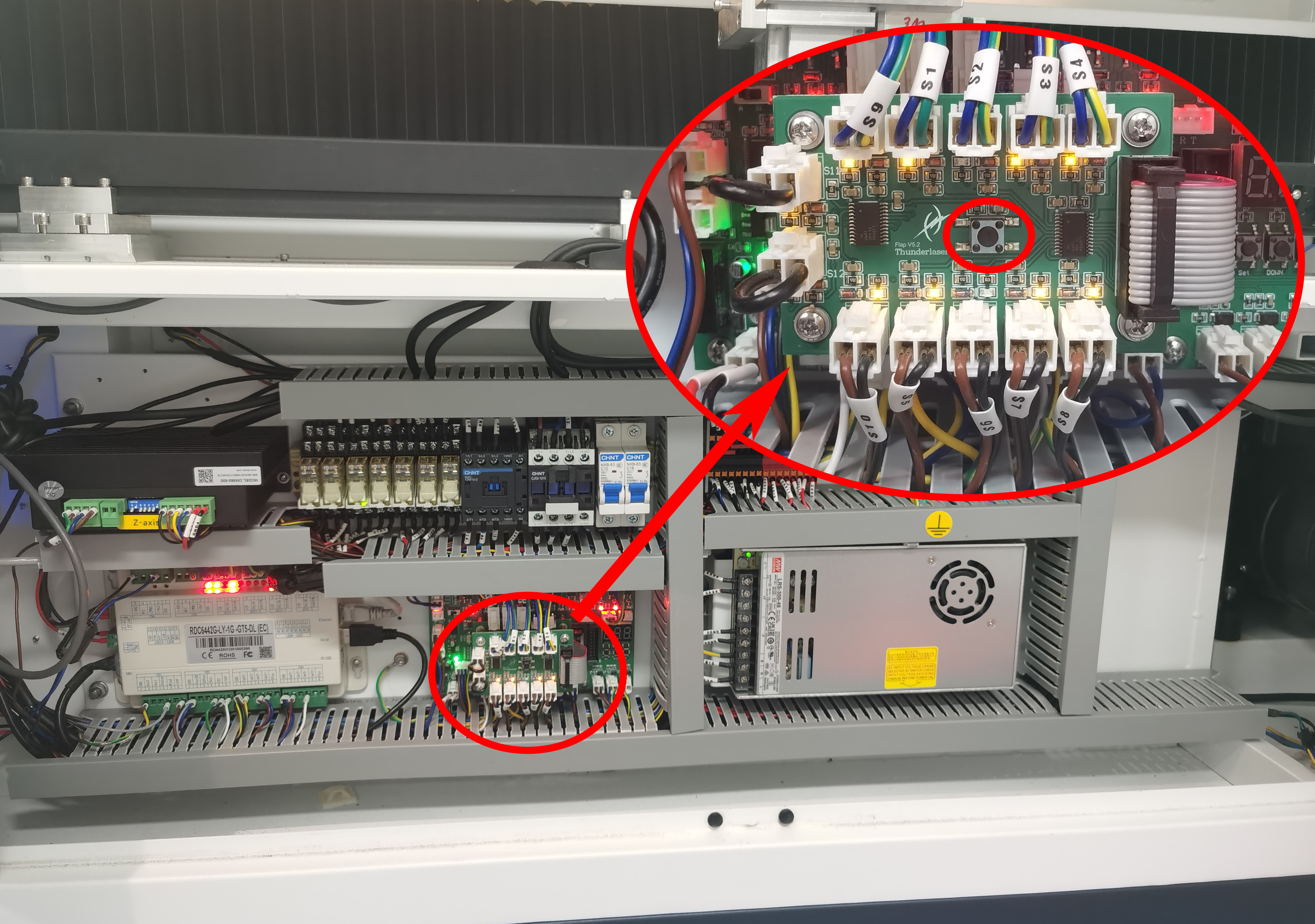
5.5. Bypass the Door Protection
IMPORTANT: Due to shutter removal, the machine's safety system locks down the interface (control panel).
|
|
The machine will reset and bypass the safety shutter check. |
|
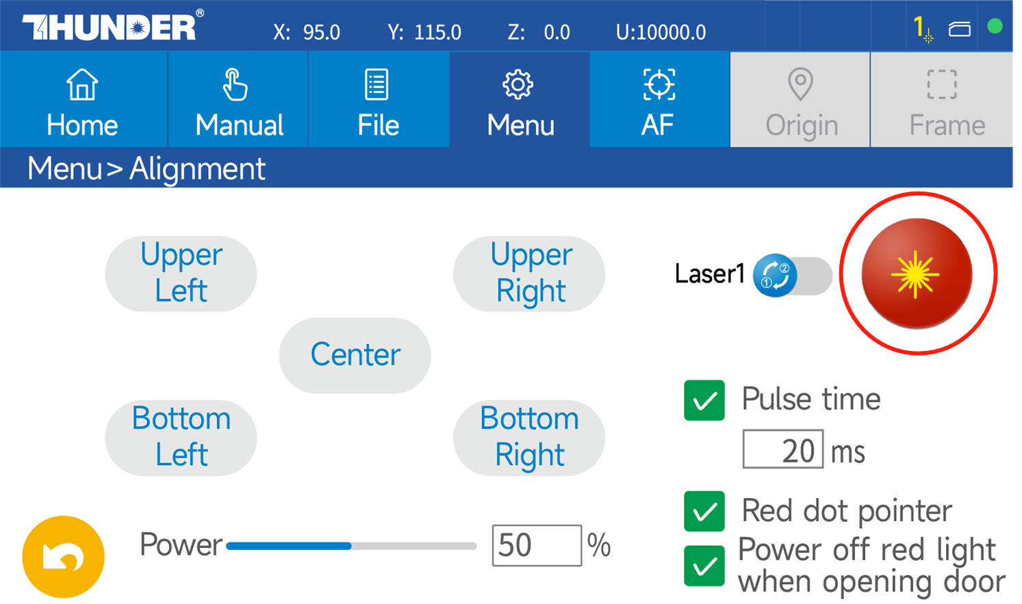
5.6. Configure Laser Parameters
On the touch panel: Navigate to Menu → Alignment Set:
|
|
⚠ WARNING
- All personnel are wearing CO2 laser safety glasses.
- Ensure the work area is clear of flammable materials.
- Beam path verified to be unobstructed.
- The emergency stop is accessible and functional.
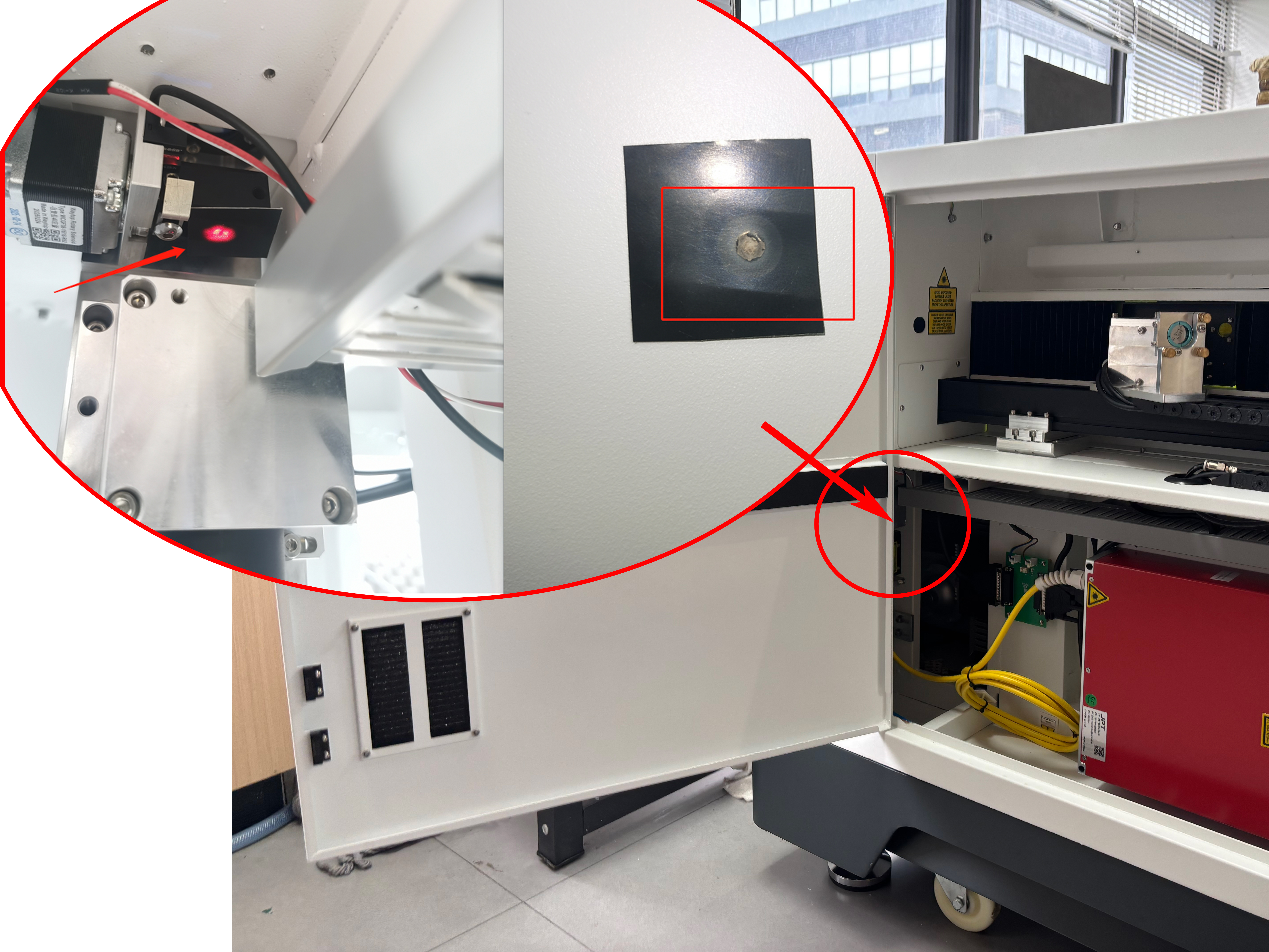
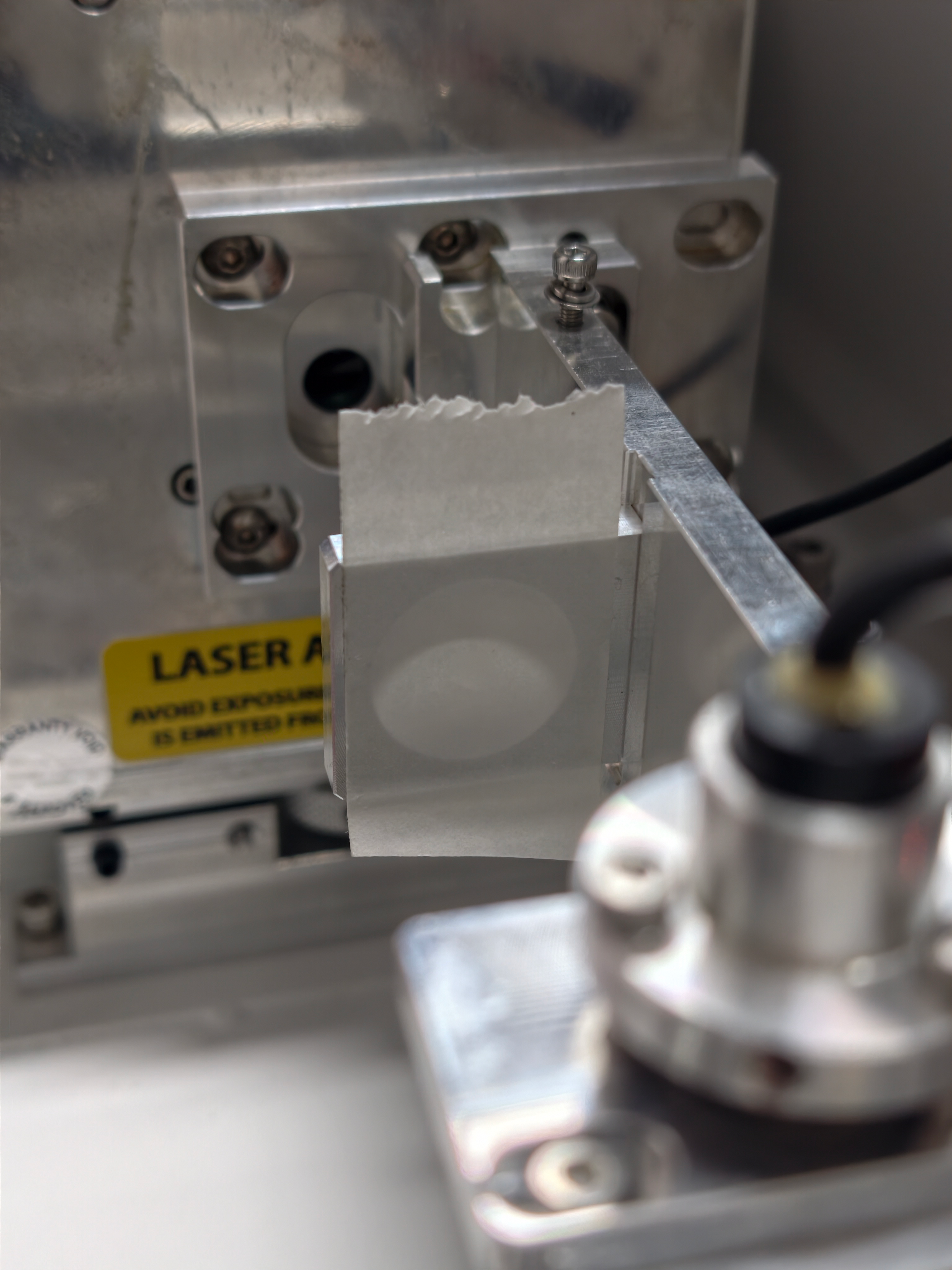
5.7. Execute Test Pulse
|
|
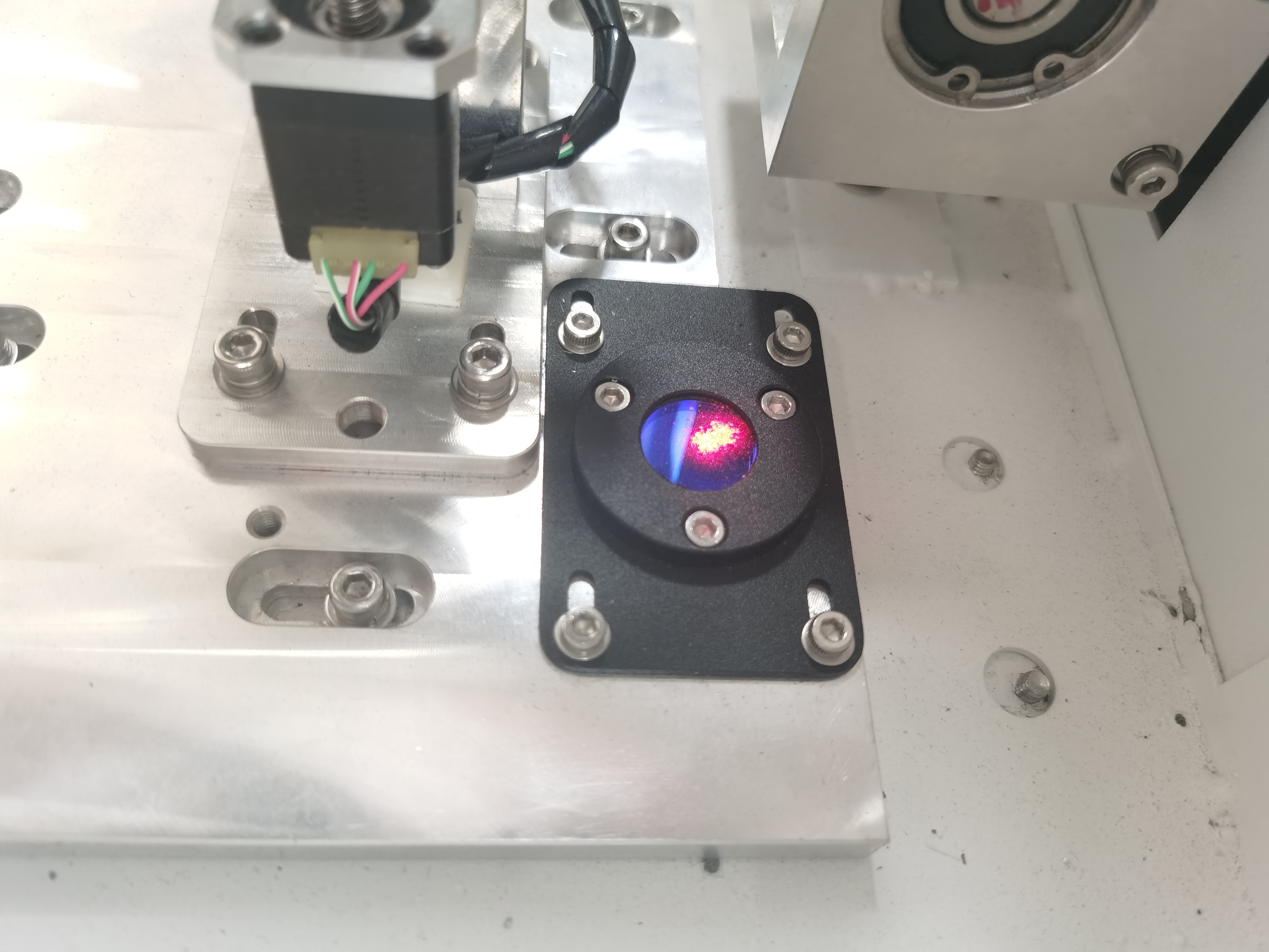
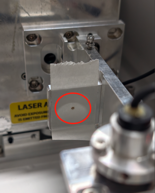
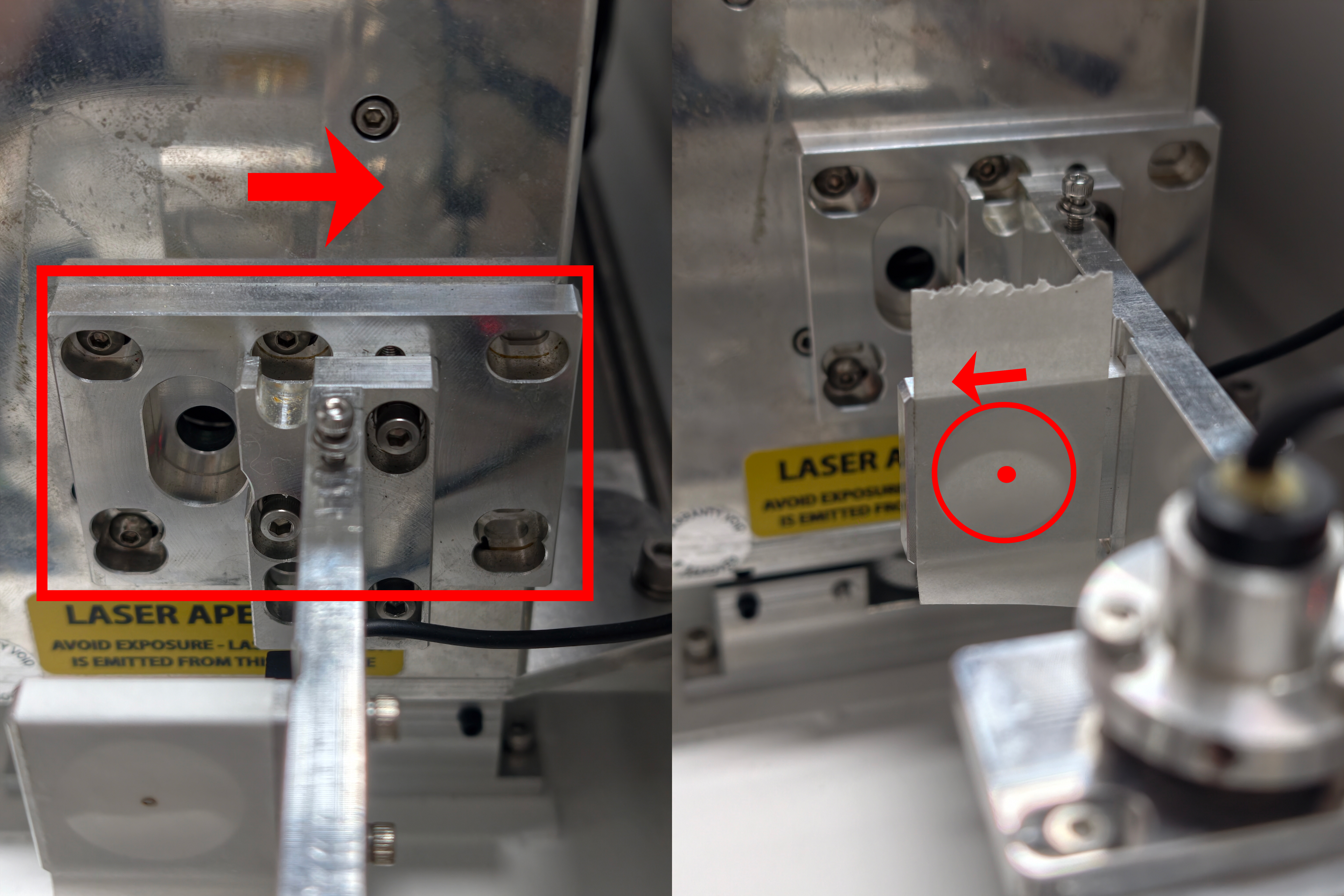
5.8. Beam Centering Analysis
Correct alignment result:
If the beam is not centered, adjustment is required. |
|
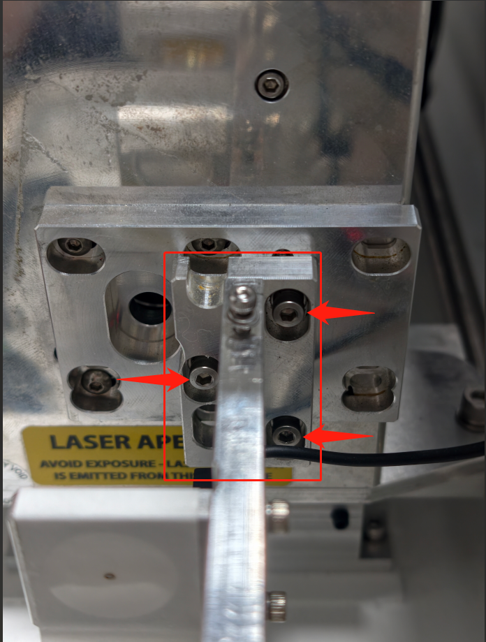
Horizontal (X-Axis) Adjustment
Note: Adjustment direction is opposite to beam movement.
|
|
|
|
|
|
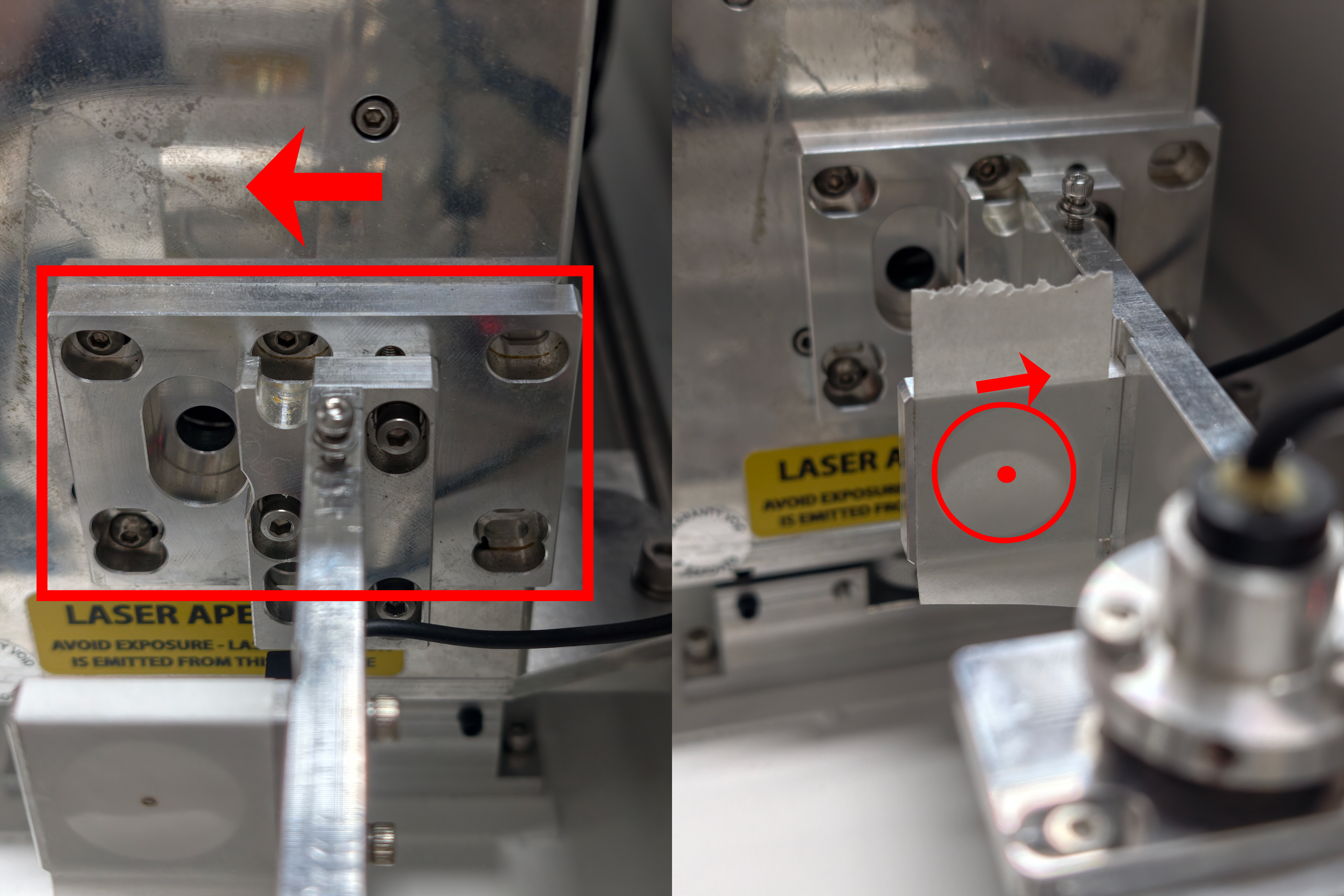
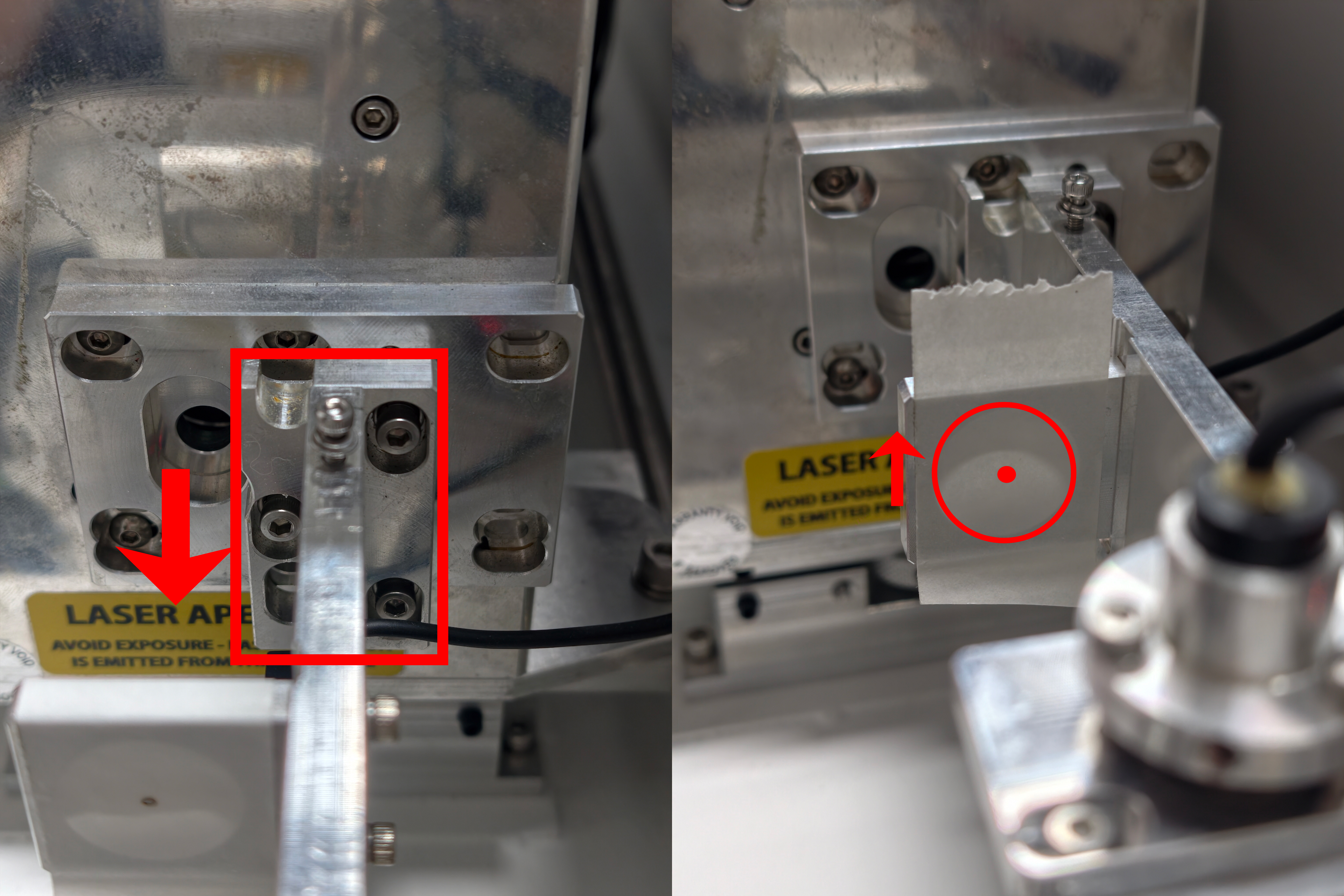
Vertical (Y-Axis) Adjustment
|
|
|
|
|
|

Repeat adjustments until the beam is perfectly centered.
Then tighten all mounting screws securely.
6. Final Reassembly Procedure
6.1. Red Dot Pointer Cable Reconnection
Reconnect the red dot pointer cable securely. |
|
6.2. The Shutter Blade Reinstall
|
|
6.3. Beam Expander Reinstall
|
|
6.4. Expander Holder Cover Reinstall
|  |
7. Realignment After Replacing the Laser
After replacing the CO2 laser, it is essential to recheck the beam path to ensure it is correct. If it is incorrect, recalibrate it according to the beam path adjustment tutorial.
Complete Guide To TITAN Series Laser Alignment
Still need help?
For specific technical questions or help requests, please open a Ticket with picture or video, so our Support team can assist you ASAP.
For the information provided in the ticket, please refer to this link:
Help Tech Support Troubleshoot Faster
END.
Related Articles
Titan and Titan Pro Laser Heads (Standard/Optional Configurations and Replacement Overview)
Preface This article describes the standard and optional laser heads (lens tubes) available for the TITAN and TITAN Pro series machines. It also explains how focus settings differ between single-source and dual-source systems, and summarizes the ...TITAN Series User's Manual
TITAN Series User's Manual Please see attached. Still need help? For specific technical questions or help requests, please open a Ticket with picture or video, so our Support team can assist you ASAP. For the information provided in the ticket, ...How to Connect fume extractor to Laser Machine
Preface: As of June 2026, the Thunder Air 700 fume extractor supports linkage control with Thunder laser machines via a signal cable. The extractor can automatically start and stop together with the laser machine, with support for pre-start and ...Complete Guide to Calibration and Use of TITAN Series Top Camera(New)
Preface Camera calibration ensures precise design alignment for the machine. This guide walks you through the process to boost accuracy and output quality. Please note that the following calibration process is for the new vision algorithm of ...How to Test Focus Distance on Titan and Titan Pro
Preface This guide explains how to test and confirm the focus distance (focal length) on Titan Series machines. Test results can be saved to the USB drive supplied with the machine. You may perform the test using RDWorks, LaserMaker, or LightBurn ...