Complete Guide To TITAN Series Laser Alignment
1 Purpose
⚠️ THIS DOCUMENT IS ONLY APPLICABLE TO TITAN PRO SERIES
The purpose of this document is to provide detailed, step-by-step instructions for aligning the optical beam paths of TITAN PRO Series laser systems. This procedure ensures the Fiber laser (Laser 2) and CO₂ laser (Laser 1) are co-aligned to the same optical path and exit the nozzle perpendicularly for optimal cutting performance.
Suggested Review Interval: This SOP should be reviewed annually or following any significant hardware revision to the TITAN PRO beam path.
2 Scope & Applicability
- Equipment: Thunder Laser TITAN PRO Series machines equipped with both Fiber (Laser 2) and CO₂ (Laser 1) sources.
- Target Audience: Certified Service Technicians and Advanced Operators.
- Prerequisites:
- Gantry Squareness: The gantry must be mechanically squared. (Critical: If the gantry is not square, alignment between Mirror 2 and Mirror 3 is impossible).
- Machine State: The machine must be powered on with interlocks bypassed for "Open Beam" operation.
3 Safety Information
⚠️ DANGER: CLASS 4 LASER RADIATION (1064nm & 10,600nm)
- Invisible Beam Hazard: The Fiber laser beam (1064nm) is invisible and can cause instant retinal damage. The CO₂ beam (10,600nm) causes severe burns and corneal damage.
- Bypassing Interlocks: This procedure requires operating with safety doors open.
⚠️ WARNING - PROCEDURAL HAZARDS
- This procedure requires bypassing safety interlocks for "Open Beam" operation. The work area must be secured.
⚠️ MANDATORY PPE (Personal Protective Equipment)
Hazard | PPE Item | Specification | Notes |
Fiber Laser (1064nm) | Laser Safety Glasses | OD ≥ 6+ @ 1064nm | Standard CO₂ glasses provide NO protection. |
CO₂ Laser (10,600nm) | Laser Safety Glasses | OD ≥ 5+ @ 10,600nm |
4 Tools and Materials Required
Item | Specification | Usage |
Hex Key Set | M3, M4 | Loosening Holder Bolts (Silver) and Slot Sensors |
Alignment Media | Black Alignment Paper | Fiber Laser (White paper will not mark visible |
Alignment Media | Double-sided Tape | CO₂ Laser spot testing |
Alignment Media | Clear Tape | CO₂ Laser spot testing on the laser head nozzle |
Test Object | Acrylic Block (20x20x10mm) | Verticality (Z-Axis) verification |
Measuring Tool | Ruler / Caliper | Measuring beam offsets and RF tube height |
5 Preparation & Critical Notes
5.1 Operational "Keys to Success."
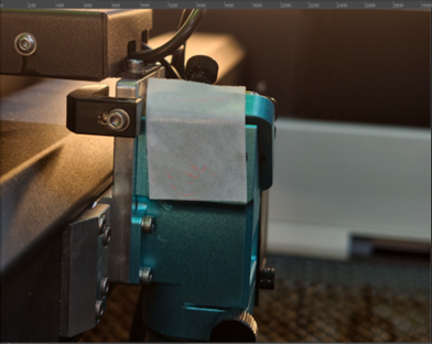
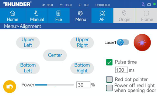
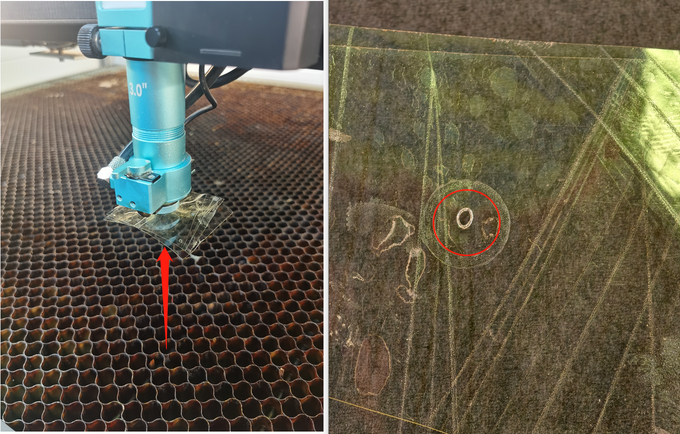
- Baseline Verification: Before loosening any screws, evaluate the current alignment status. Place tape over the Mirror 3 entry aperture and pulse the laser at all four corners of the work area to determine if adjustment is actually required.
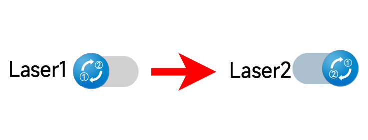
- Order of Operations: Always align the Fiber (Laser 2) path first to establish the master reference, then align the CO₂ (Laser 1) path to match it.
- Mirror Progression: Work sequentially from the source. Start at Mirror 1 and move forward. Never proceed to the next mirror until the current stage is perfectly aligned.
- The Red Dot Rule: The Red Dot is secondary. Never align mirrors to the Red Dot, as it does not represent the actual cutting beam path. Adjust the Red Dot Pointer only as the final step of the process.
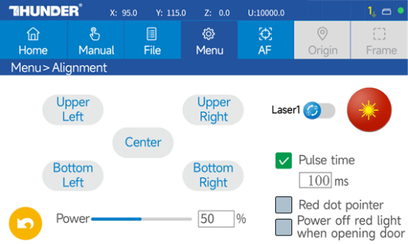
- Power Settings: Use the minimal power required to make a visible mark (approx. 30%). High power will burn through the tape/paper and obscure accuracy.
- Hardware Handling: When tightening silver mounting bolts, do not over-tighten. "Snug" is sufficient to hold the position without warping the brackets.
6 PROCEDURE A: FIBER LASER ALIGNMENT (LASER 2)
Objective: Establish the Master Beam Path. The Fiber Laser is the Reference.
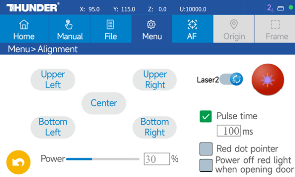
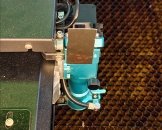
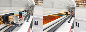
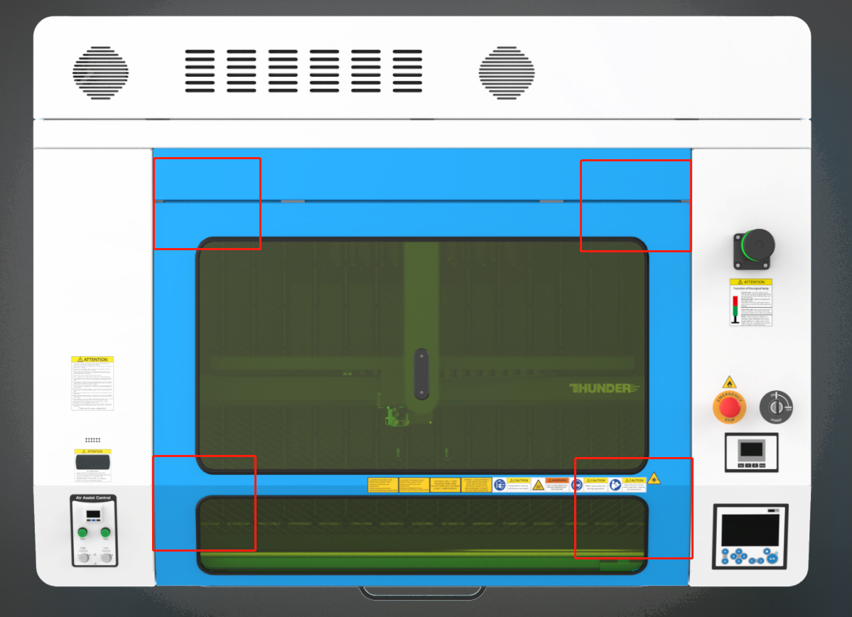
6.1 Machine Setup
|
|
| 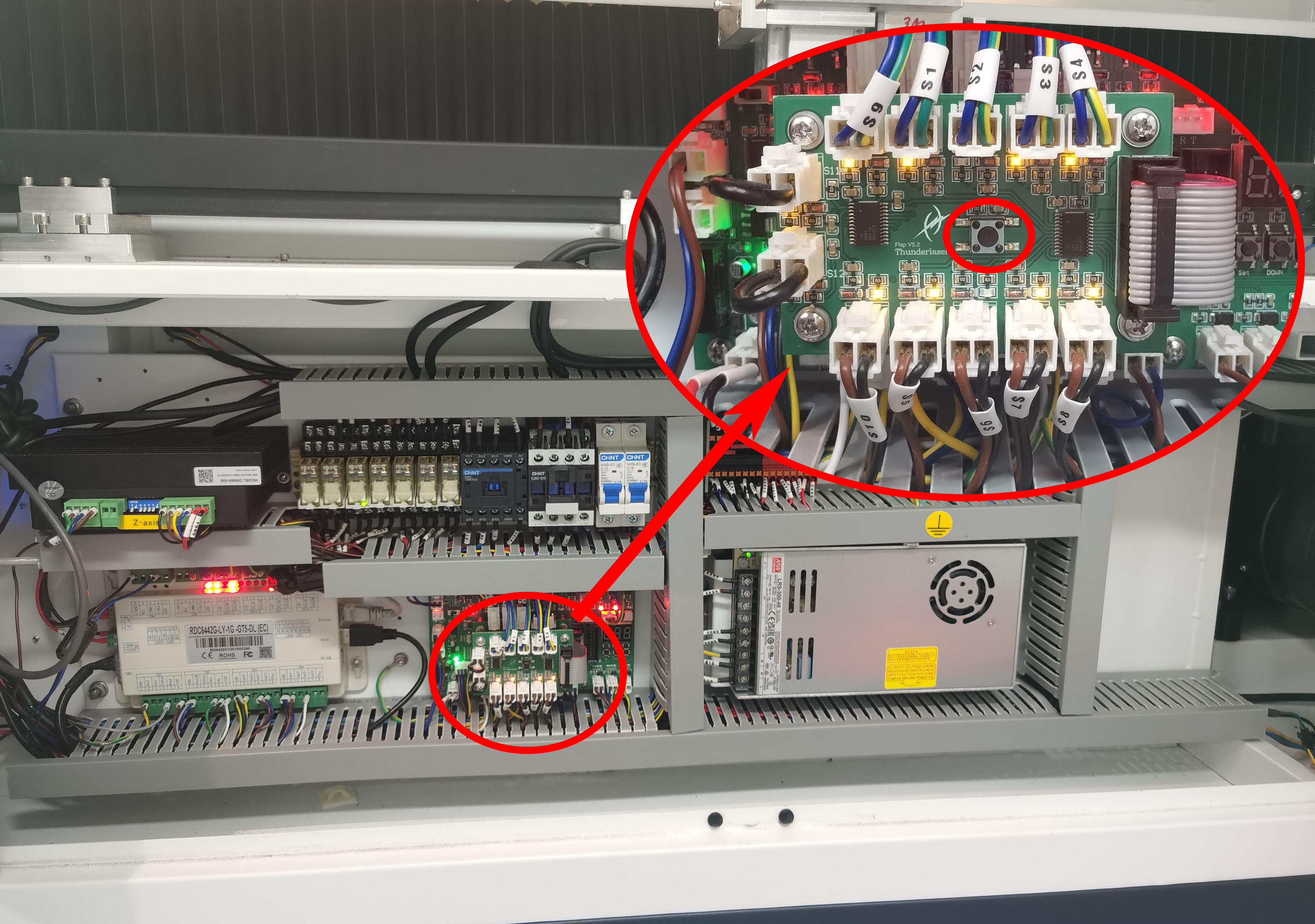 |
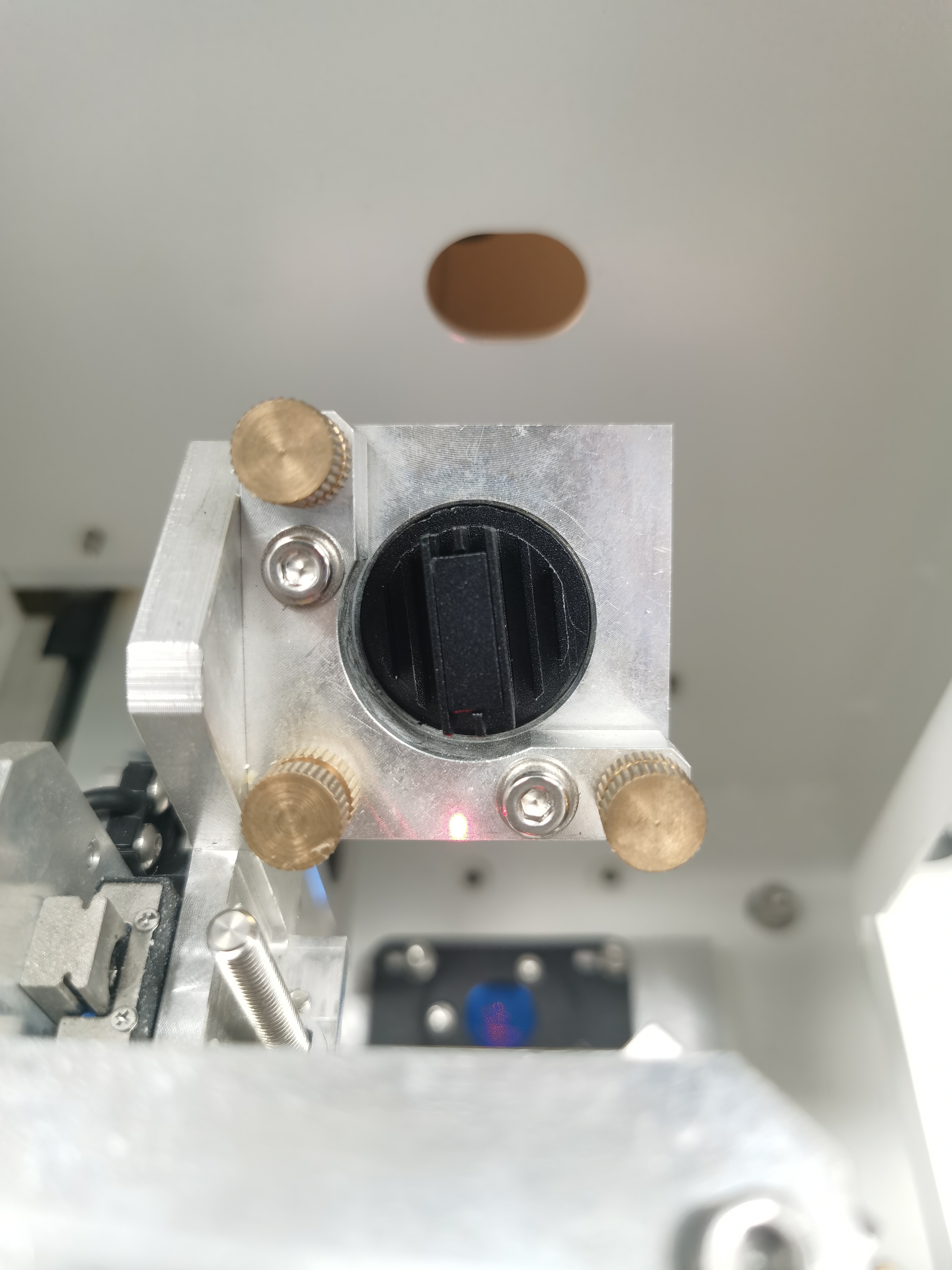
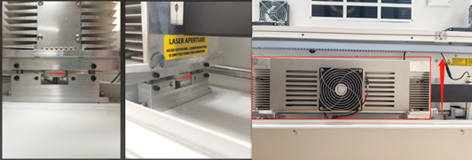
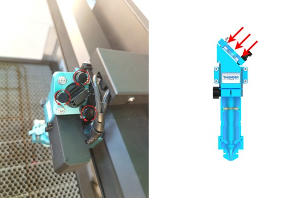
6.2 Step 1: Check the Laser Shutter Opening
|
|
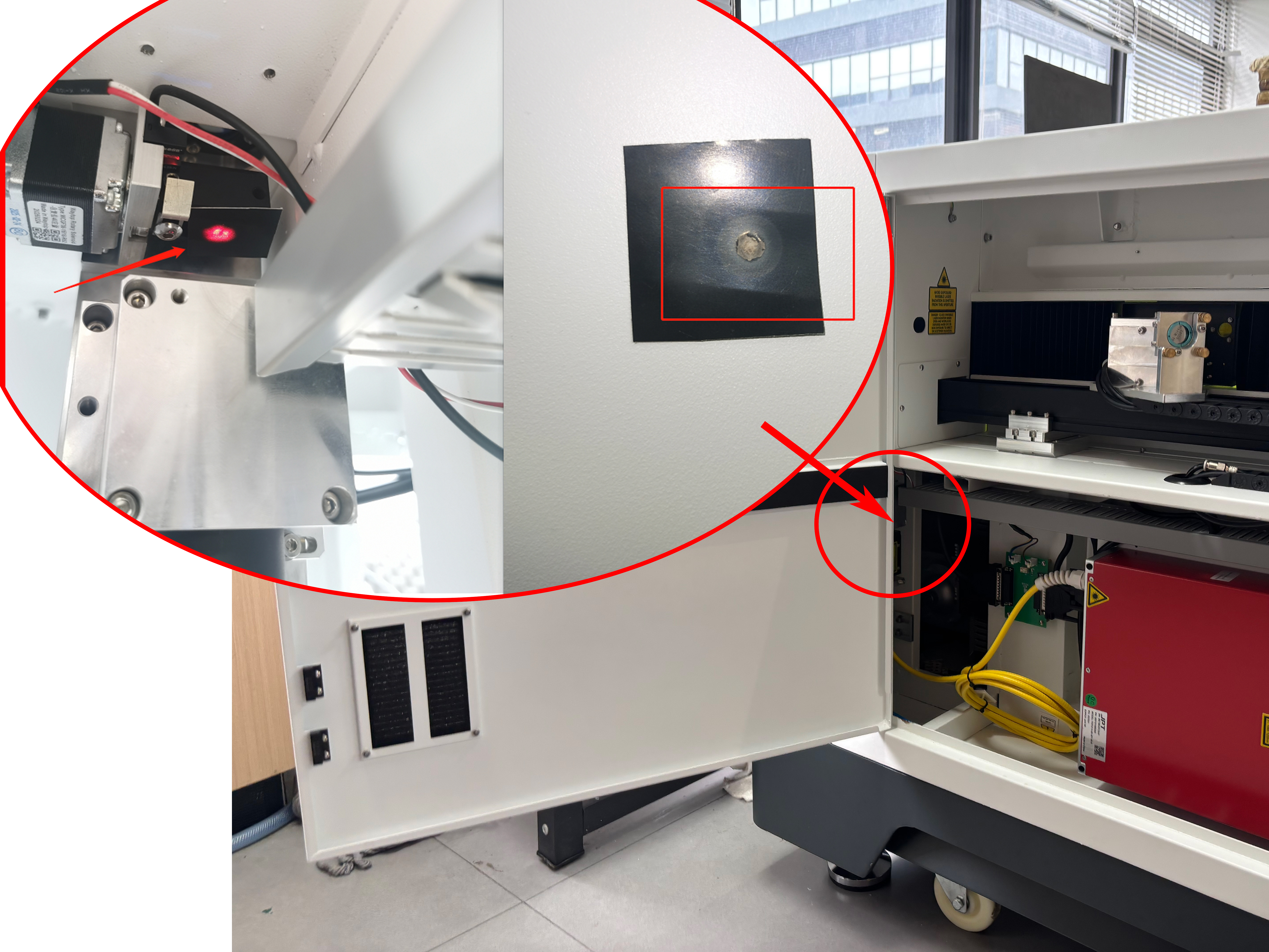
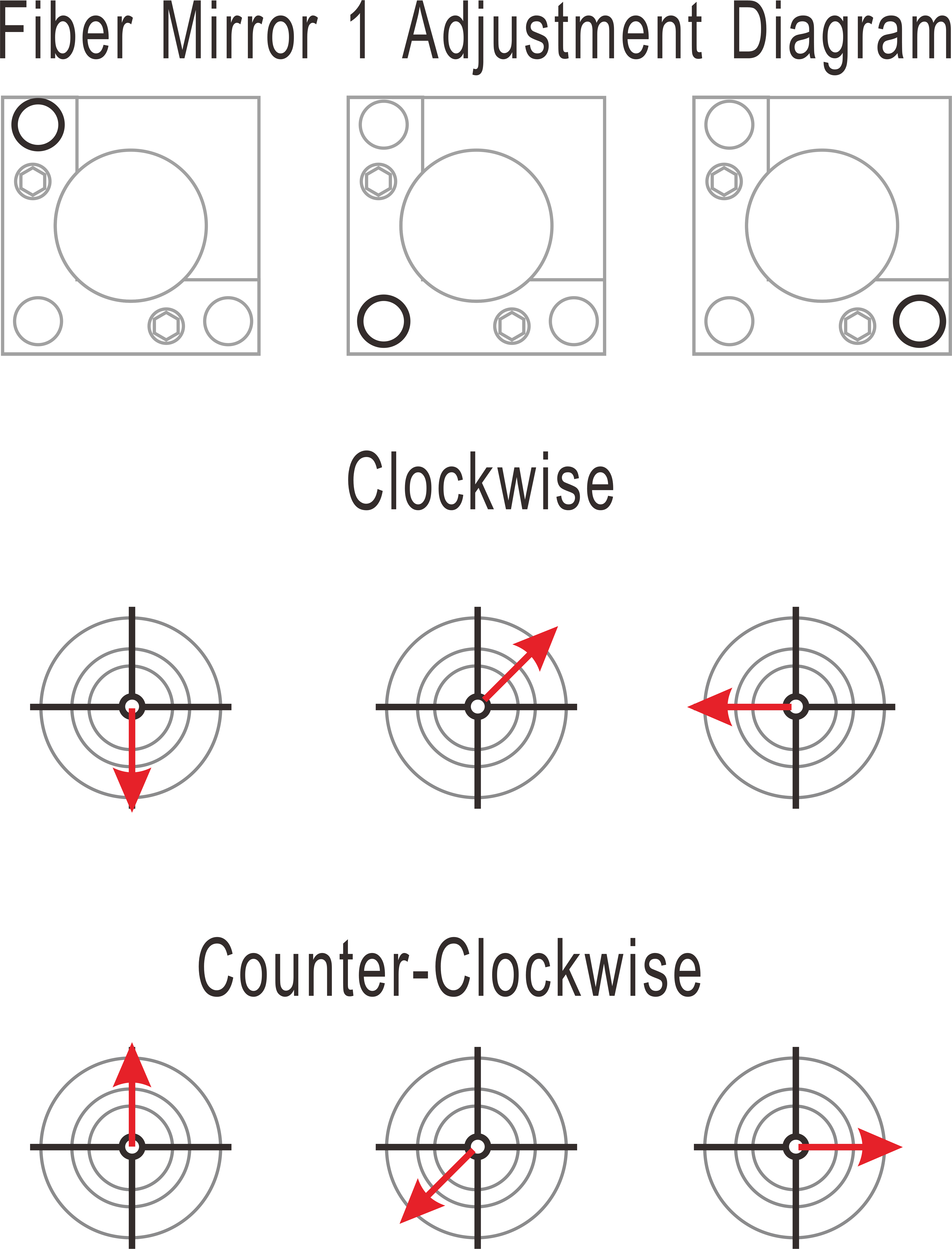
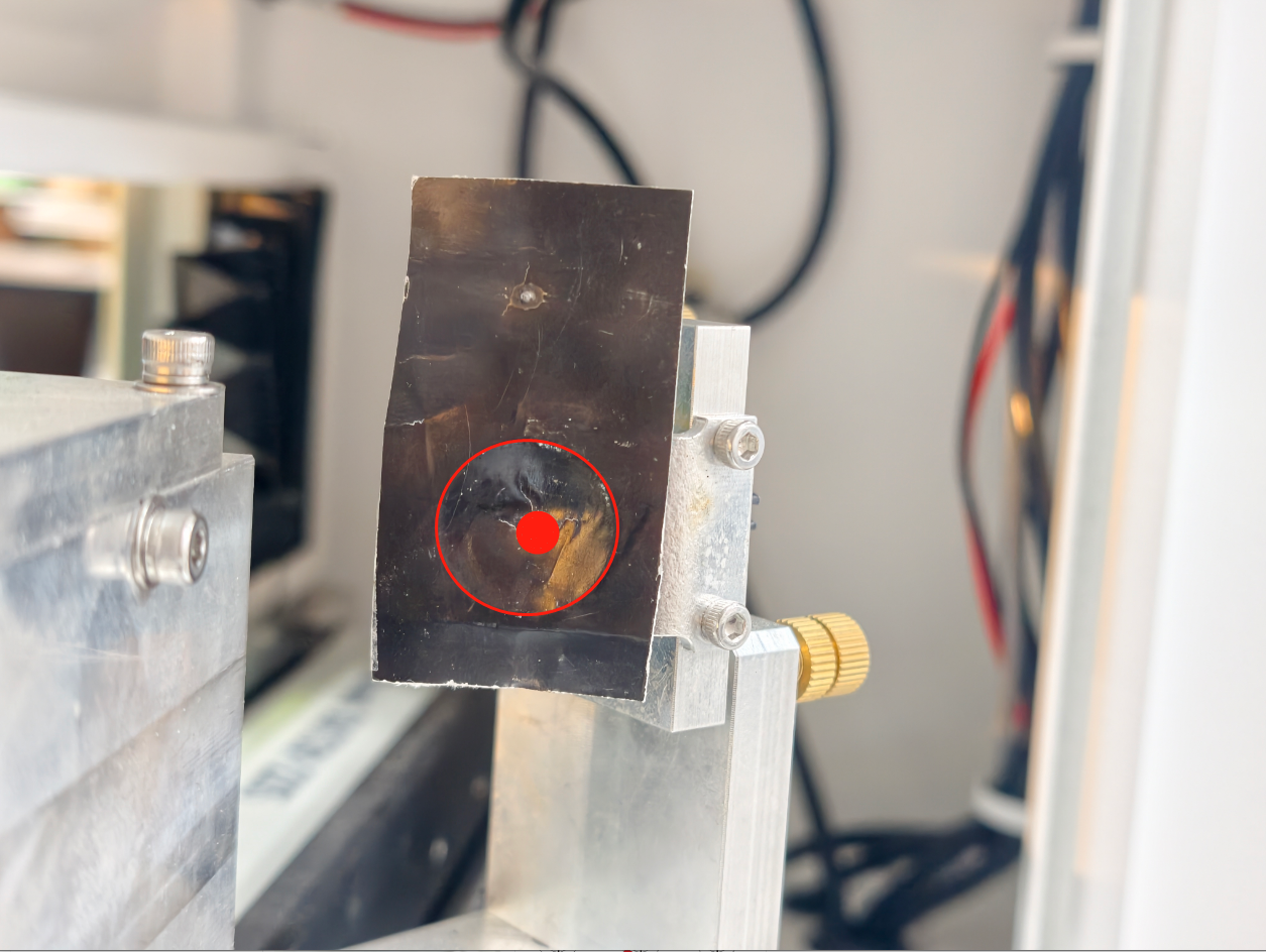
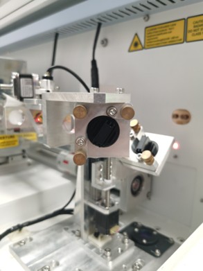
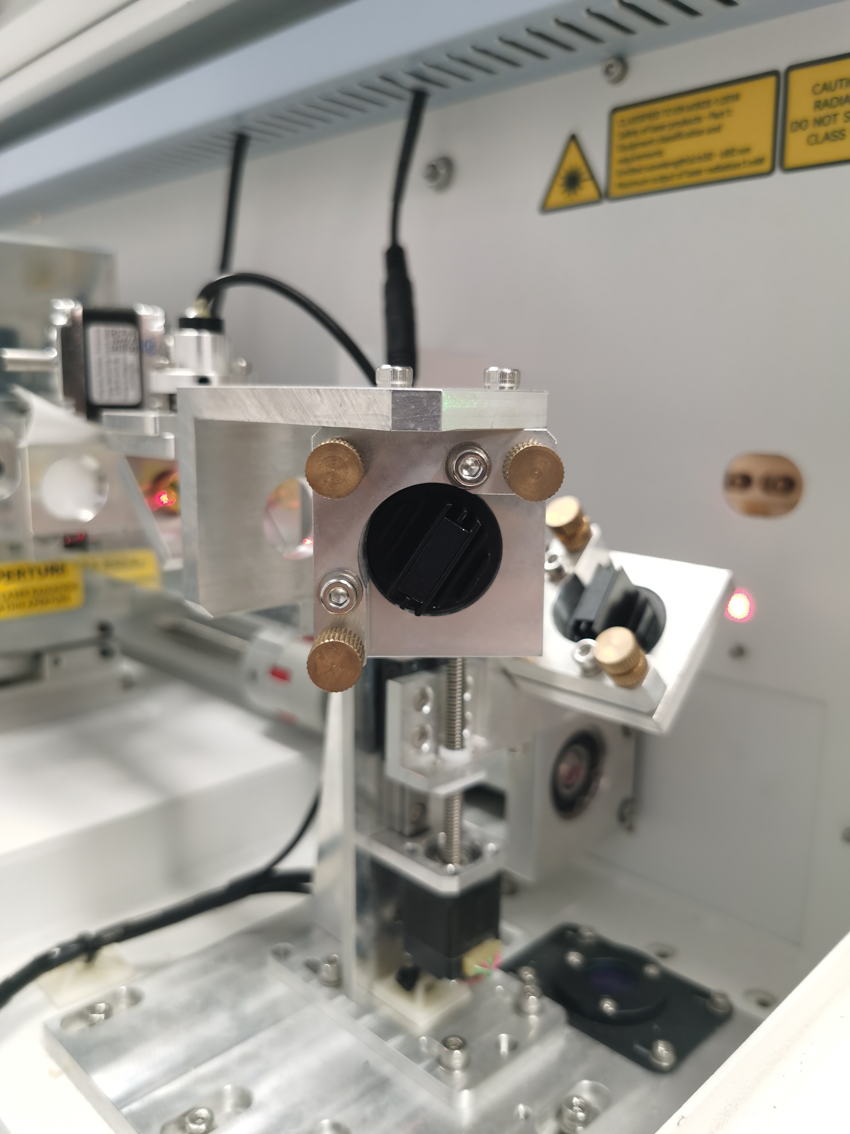
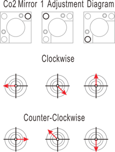
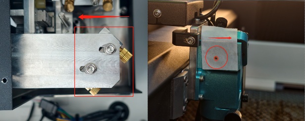
6.3 Step 2: Centering Mirror 1 (Source Output)
Objective: Ensuring the beam hits the center of the mirror 1 frame.
Criterion: The beam must pass through the shutter easily and be centered within 2 mm.
|
⚠️ Adjusting the large mounting bracket of Fiber Mirror 1 may cause excessive shifts later. This is usually pre-set. Avoid this unless absolutely necessary.
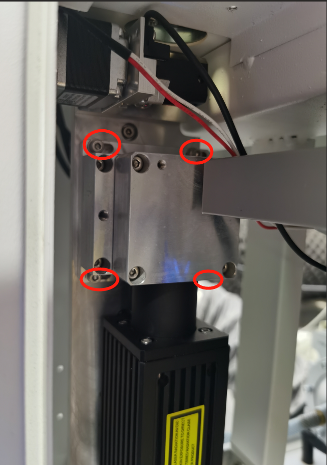
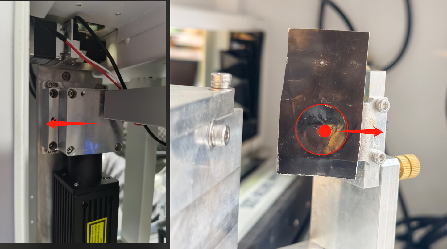
6.3.1 Horizontal (X-Axis) Offset
Loosen 4 bolts on the Mirror 1 mounting bracket. |
|
Move Mounting Bracket Left → Mark shifts Right | 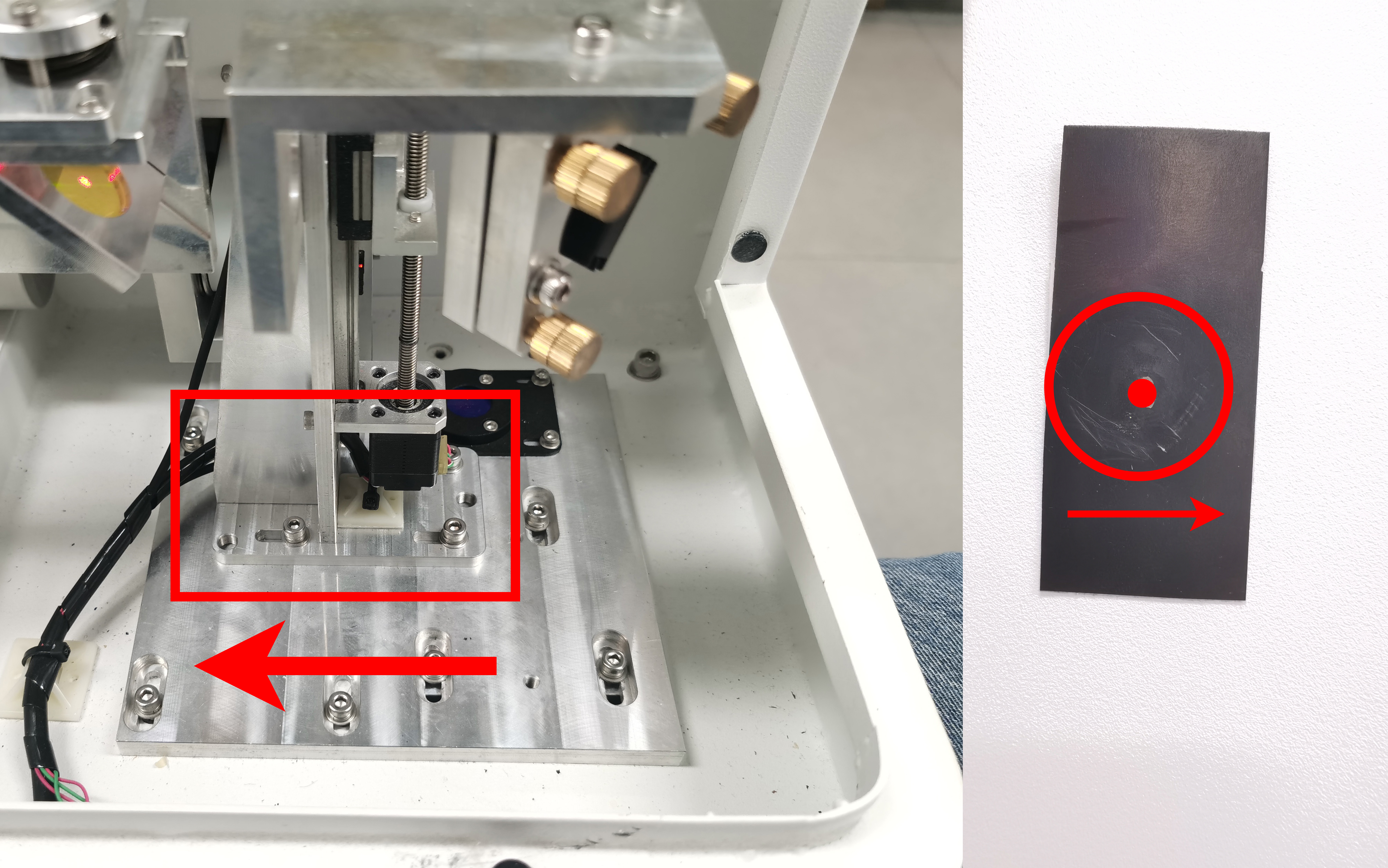 |
Move Mounting Bracket Right → Mark shifts Left |
|
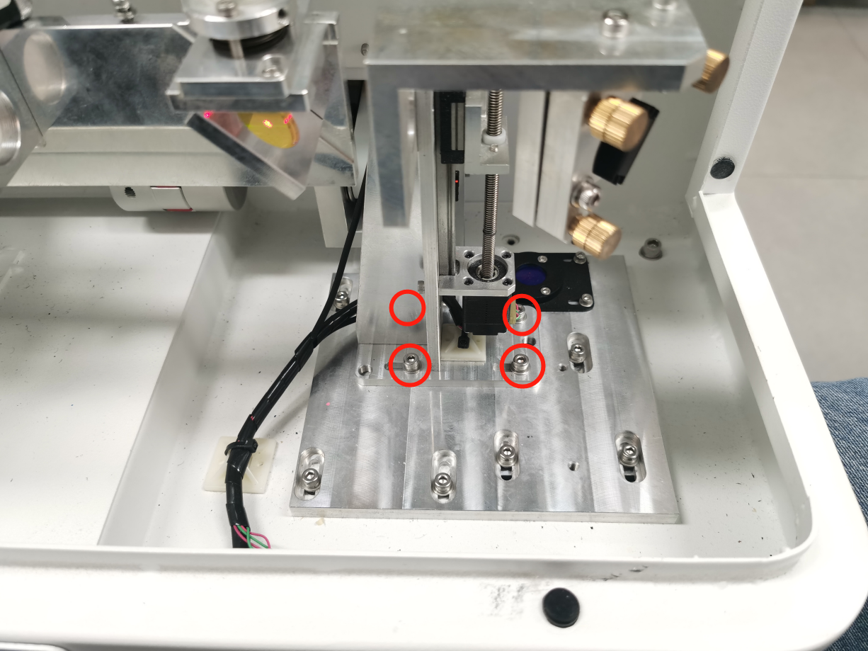
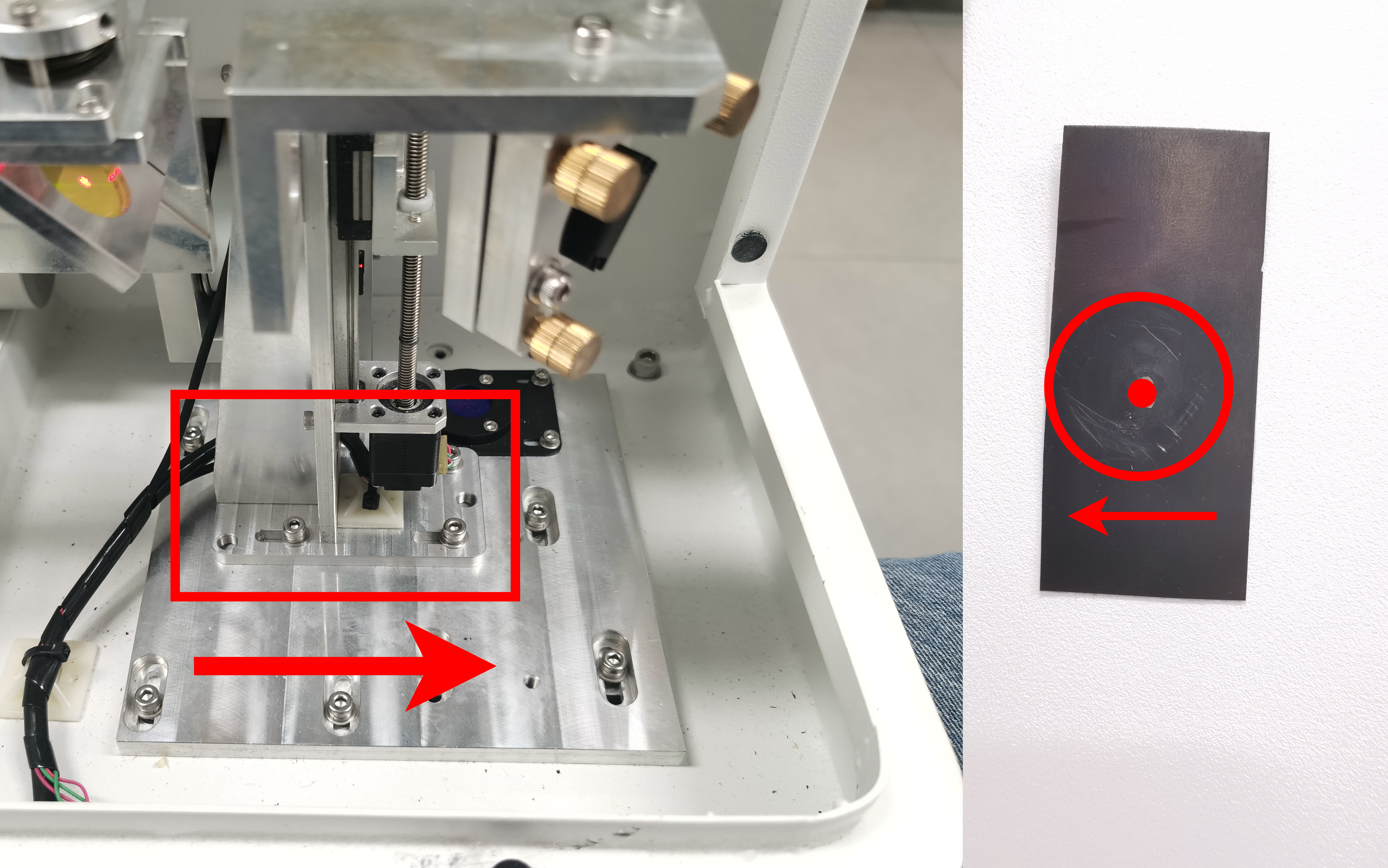
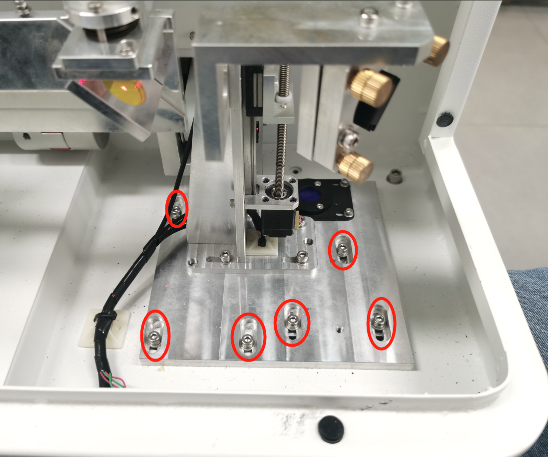
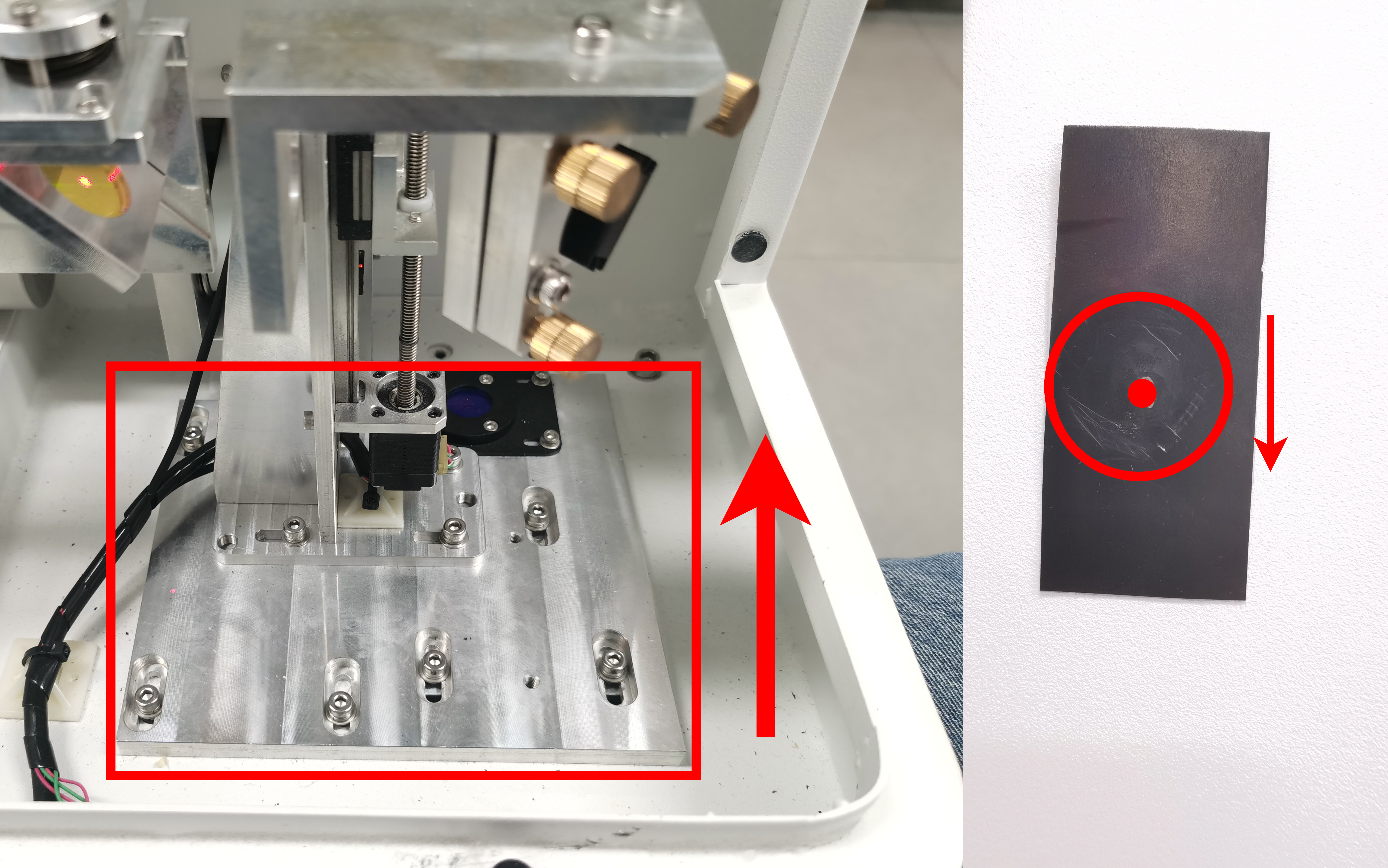
6.3.2 Vertical (Y-Axis) Offset
Loosen 7 bolts on the Mirror 1 mounting bracket holder. |
| |
Move Holder Forward → Mark shifts Down |
| |
Move Holder Backward → Mark shifts Up | 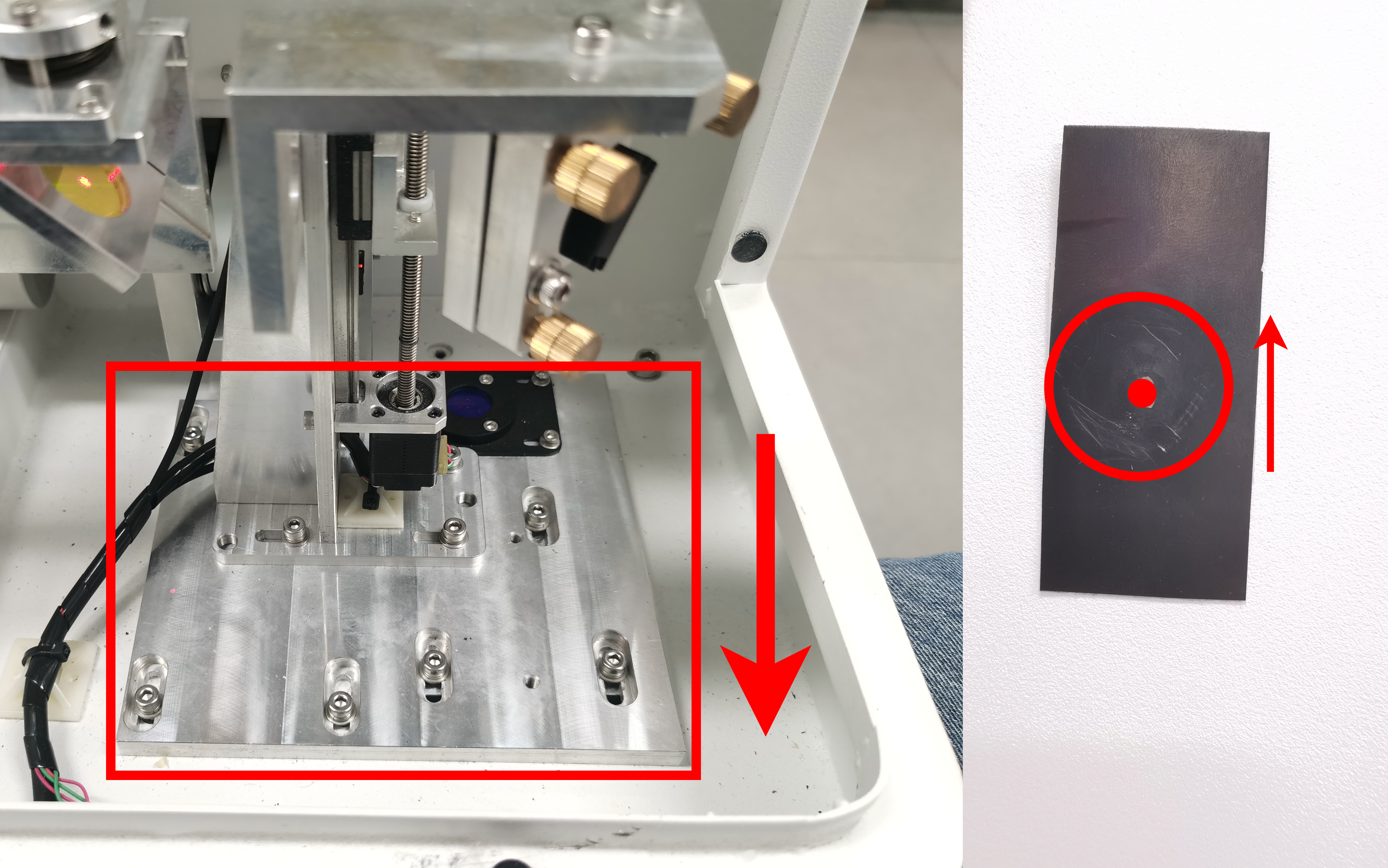 | |
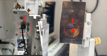
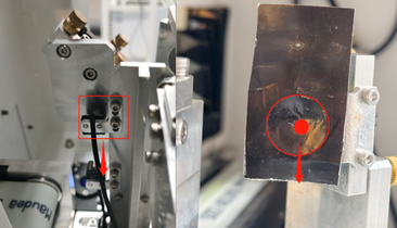
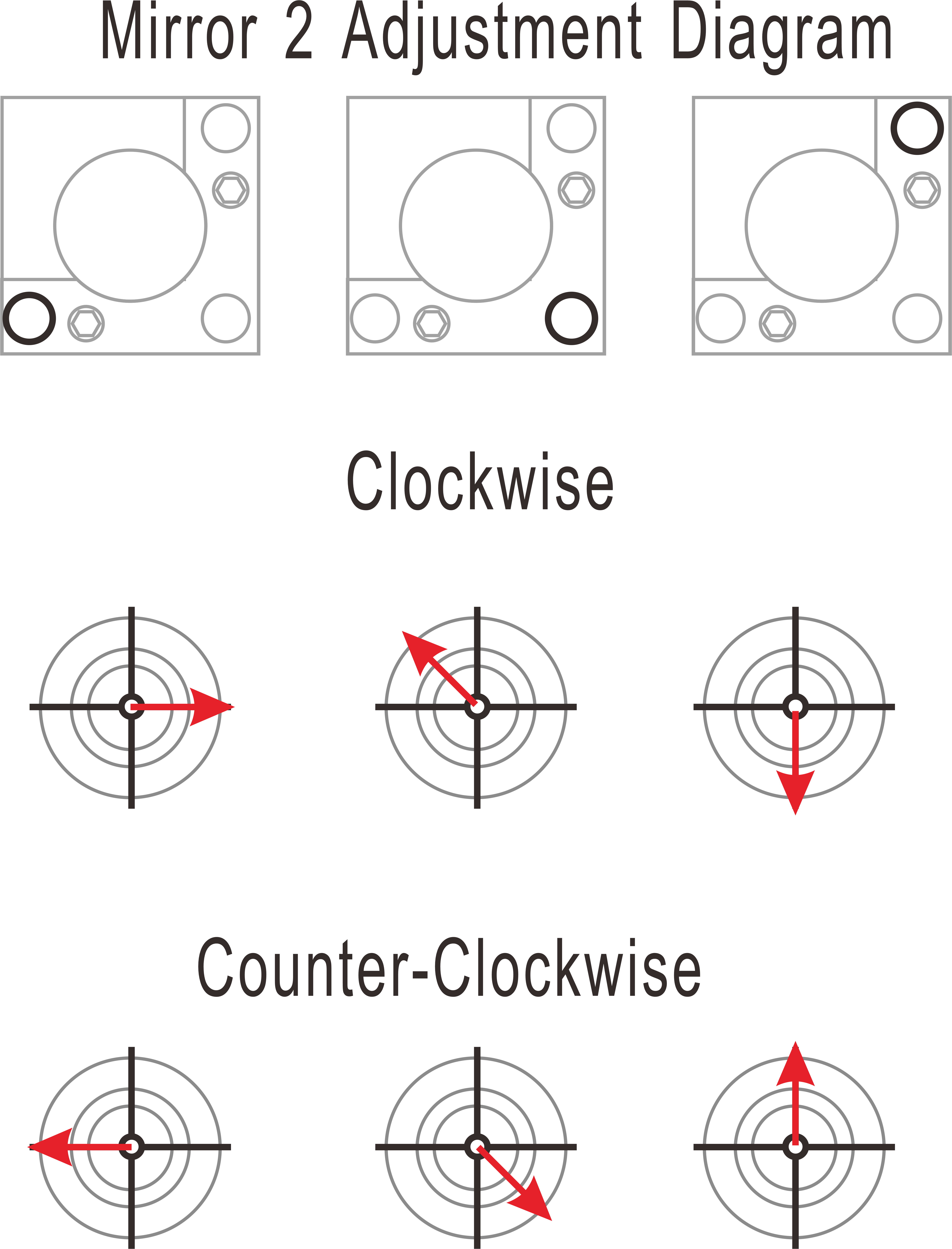
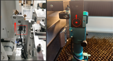
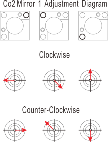
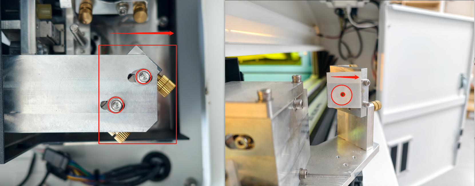
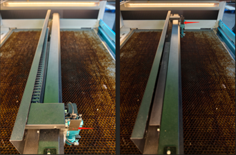
6.4 Step 3: Mirror 2 Alignment (Y-Axis Angular)
Objective: Aligning the beam travel from Rear to Front.
|
|
|
|


6.4.1 Adjustment (If dots do not overlap):
|
|
6.5 Step 4: Centering on Mirror 2 (Translational)
Objective: Ensuring the beam hits the center of the mirror frame
Criterion: Beam must be centered within 2 mm.
|
|
6.5.1 Horizontal (X-Axis) Offset
Loosen 4 bolts on the Fiber Laser Output Head Holder. |
|
Move Holder Right → Mark shifts Left. | 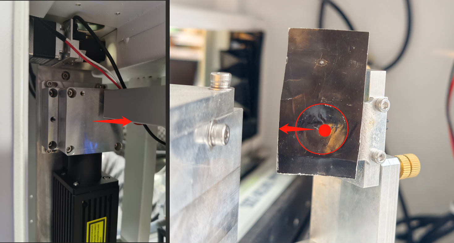 |
Move Holder Left → Mark shifts Right. |
|
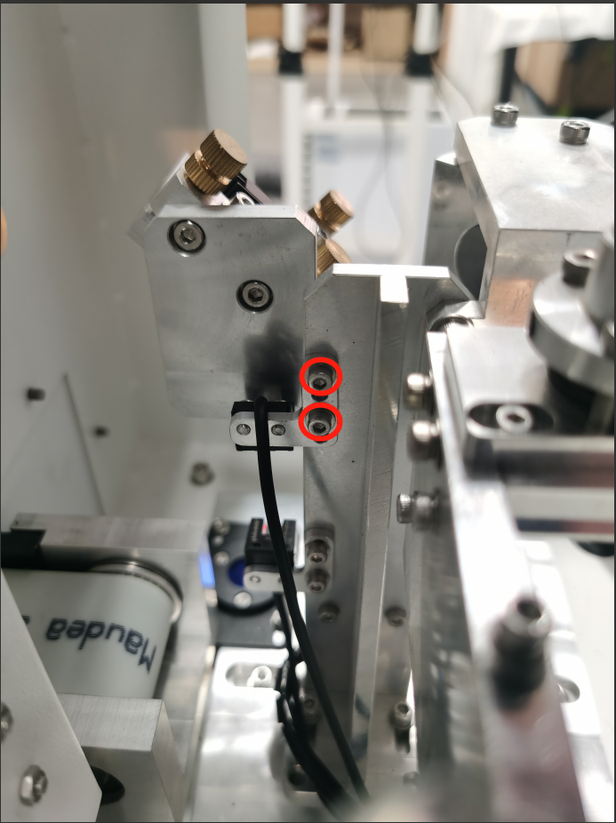
6.5.2 Vertical (Y-Axis) Offset
Loosen 2 silver bolts on Upper Limit Slot Sensor (Fiber Mirror 1). |
|
Move Limit Sensor Up → Mark moves Up. |
|
Move Limit Sensor Down → Mark moves Down. |
|
CRITICAL: After each adjustment, switch to Laser 1 then back to Laser 2 on the Touch Panel to Re-Home. |
|
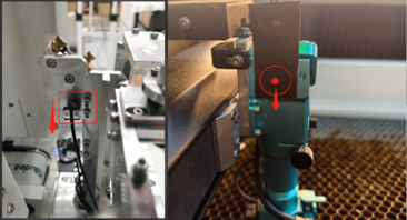
6.6 Step 5: Mirror 3 Alignment (X-Axis Angular)
Objective: Aligning the beam travel from Left to Right.
|
|
|
|


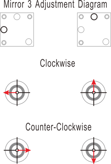
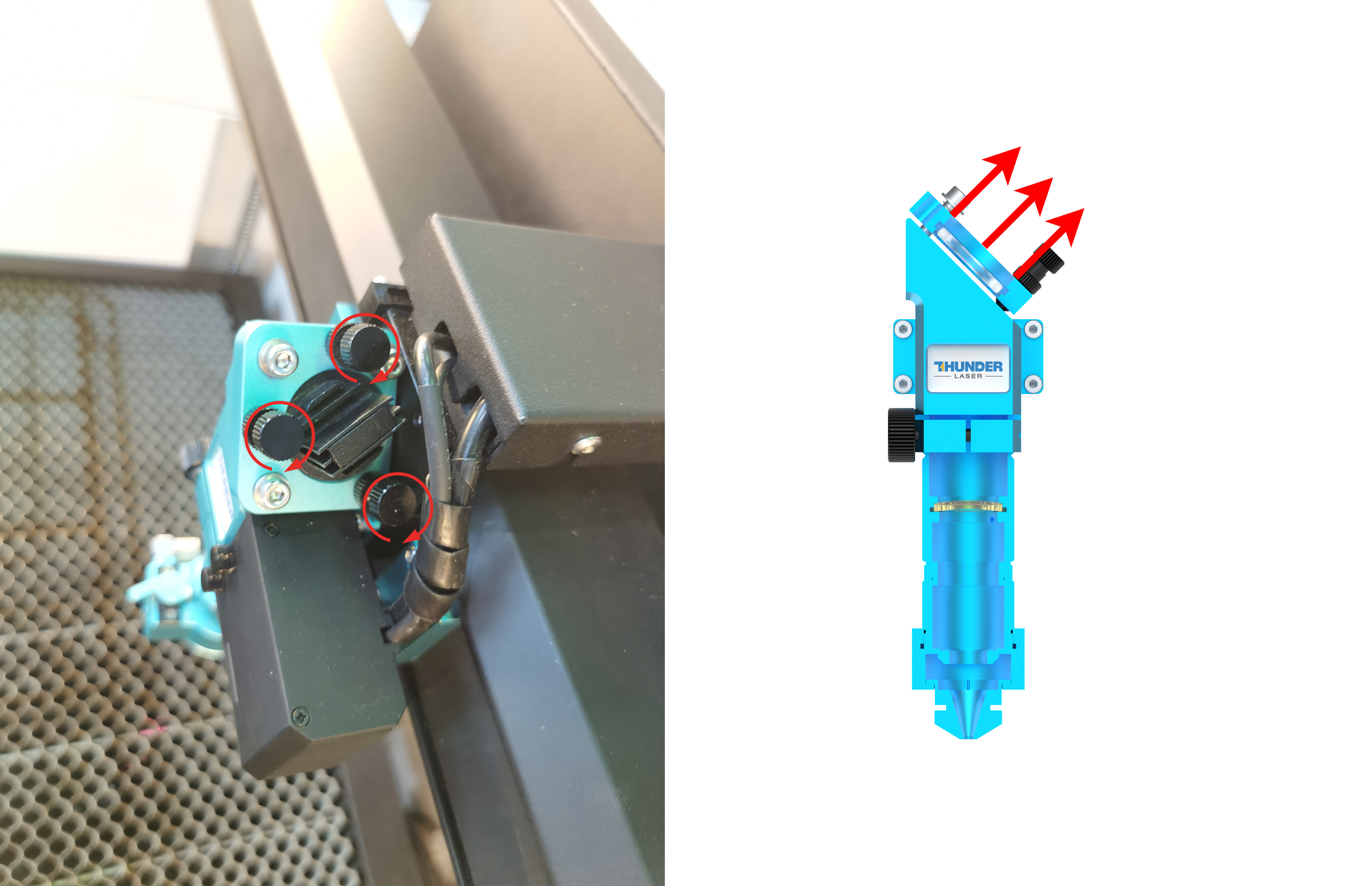
6.6.1 Adjustment (If dots do not overlap):
|  |
|
|
Once confirmed, tighten silver locking bolts and all brass screws on Mirror 2, and check again to make sure that the pulse marks at all four corner positions on Mirror 3 remain aligned. | |

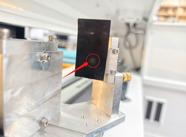
6.7 Step 6: Centering on Mirror 3 (Translational)
Objective: Ensuring the beam enters the lens centered.
Criterion: Beam must be centered within 0.5 mm.
|
|
6.7.1 Horizontal (X-Axis) Offset
Loosen 2 bolts on the Mirror 2 Holder. |
|
Move Holder Right → Beam shifts Right. |
|
Move Holder Left → Beam shifts Left. |
|
Tighten bolts and all brass screws immediately after setting. | |

6.7.2 Vertical (Y-Axis) Offset
Loosen 2 sensor bolts on Upper Limit Slot Sensor (Fiber Mirror 1). |
|
Move Limit Slot Sensor Up → Beam shifts Up. |
|
Move Limit Slot Sensor Down → Beam shifts Down. |
|
CRITICAL: After each adjustment, switch to Laser 1 then back to Laser 2 on the Touch Panel to Re-Home. |
|
Once the alignment is complete, tighten the mounting bolts of Mirror 2’s Holder and the slot sensor fixing bolts on the Fiber Mirror 1 Holder. After tightening, pulse again to verify whether the spot has shifted. | |
⚠️ CRITICAL LOCK-DOWN: After completing the alignment of the first laser source, make sure all bolts on Mirror 2’s holder and mirror are fully tightened.
7 PROCEDURE B: CO₂ LASER ALIGNMENT (LASER 1)
Objective: Align the CO₂ beam to overlap the established Fiber beam.
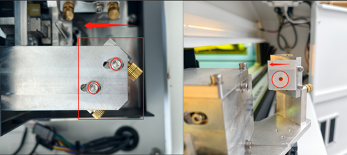
7.1 Step 1: Mirror 2 Alignment (Y-Axis Angular)
|
|
|
|
|
|

7.1.1 Adjustment (If dots do not overlap):
|
|
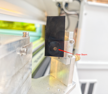
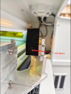
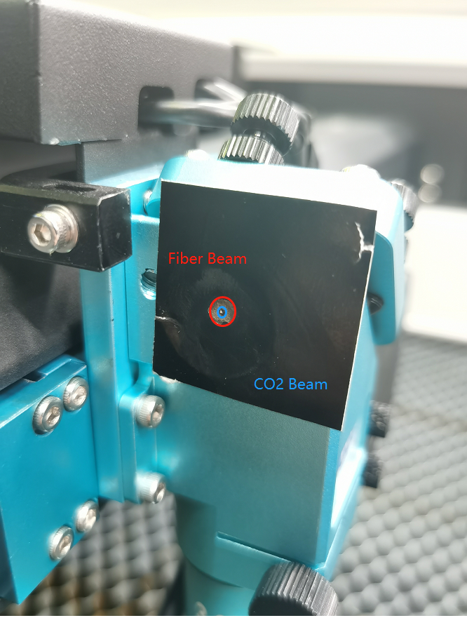
7.2 Step 2: Co-Location (Fiber + CO₂) at Mirror 2
Goal: The CO₂ spot must sit exactly on top of the Fiber spot.
|
|
|
Fiber Mark |
|
CO2 Mark |
|
Fiber Mark CO2 Mark |


7.2.1 Horizontal (X-Axis) Offset
Loosen the entire CO₂ Mirror 1 Holder. |
|
Slide Holder Left → Mark shifts Left. |
|
Slide Holder Right → Mark shifts Right. |
|

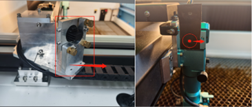
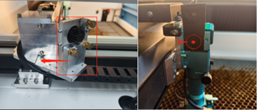
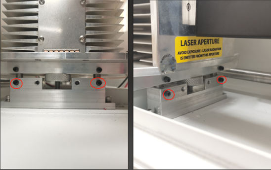
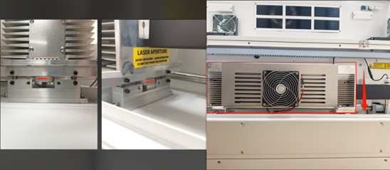
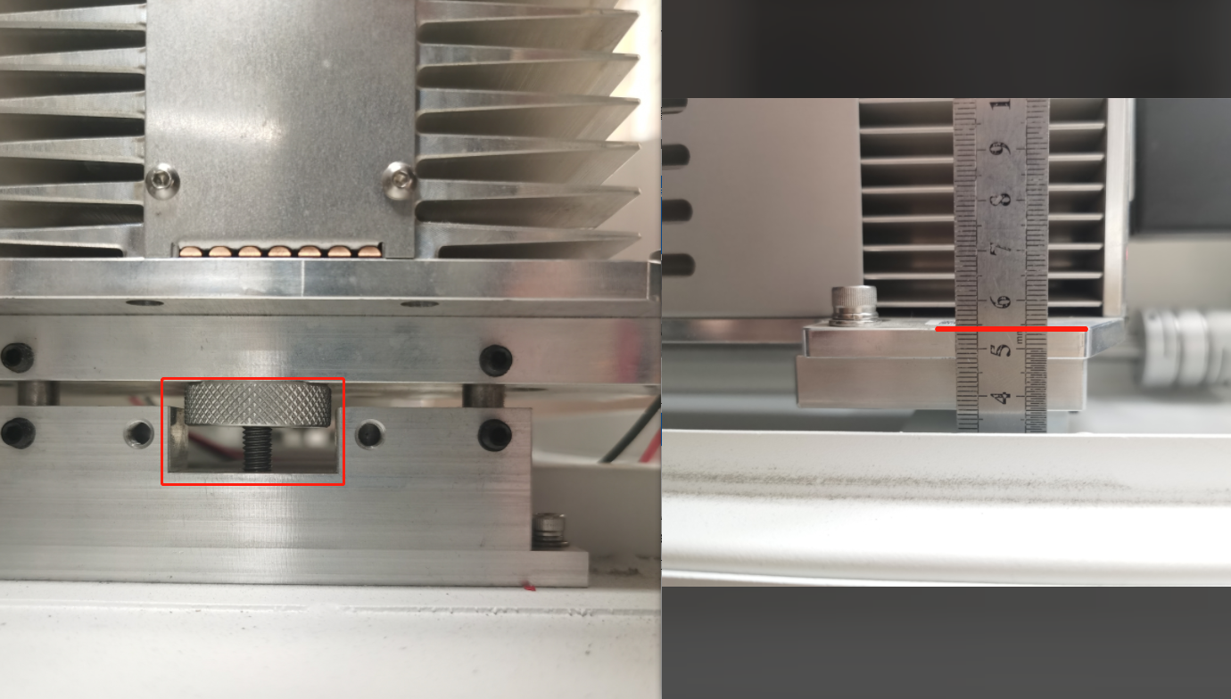
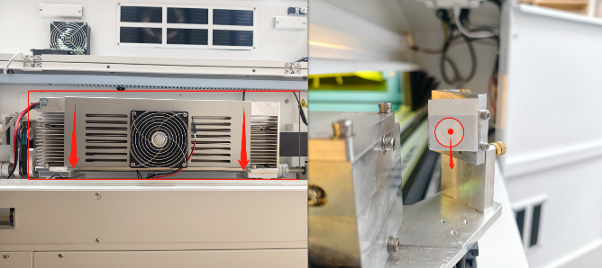
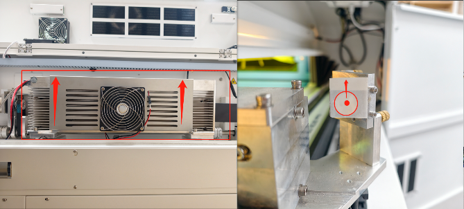
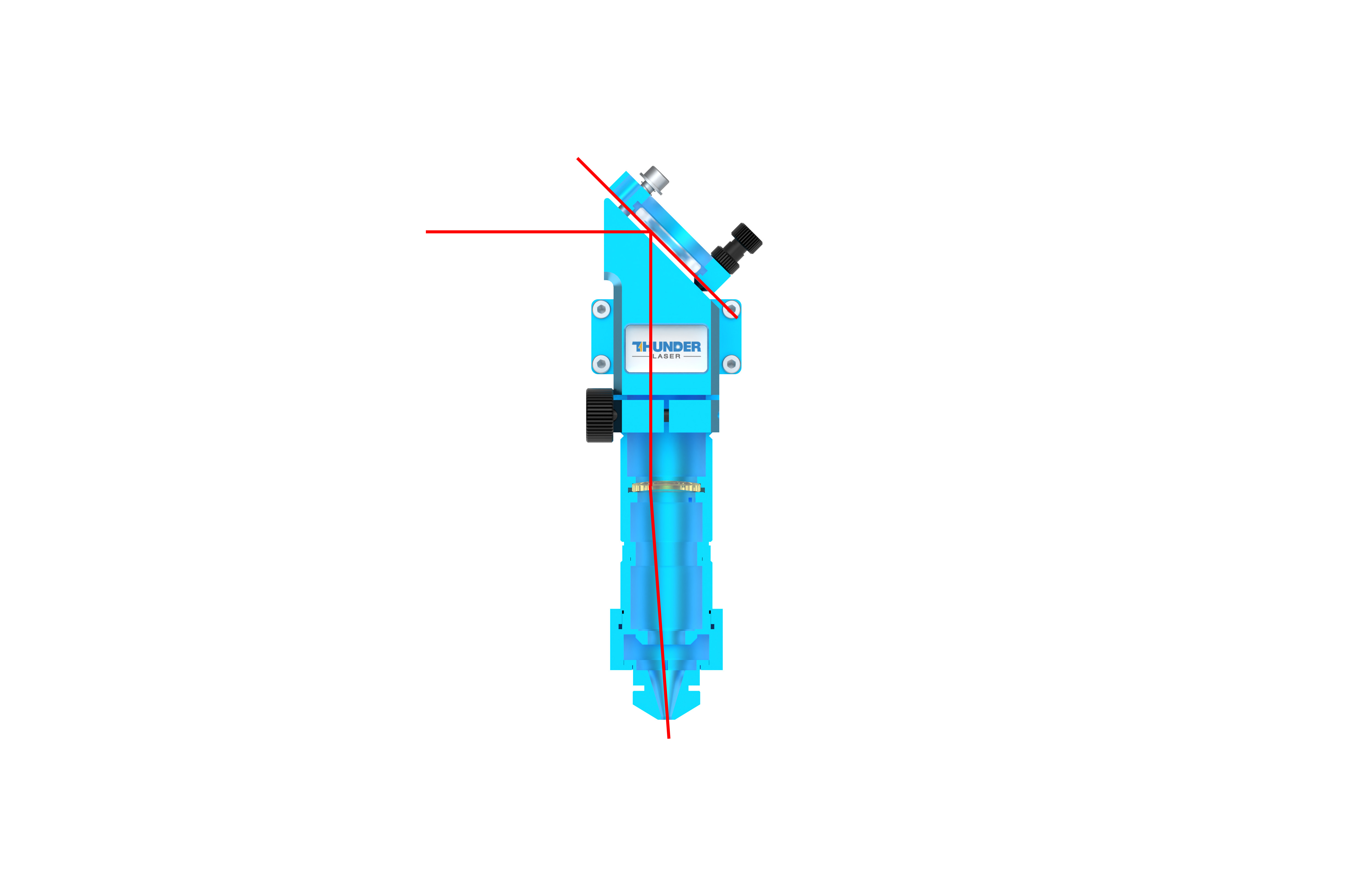
7.2.2 Vertical (Y-Axis) Offset
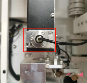
Loosen 4 set bolts on RF Tube Holder. |
|
Important: Use a ruler to ensure the front and Rear knobs are turned equally. |
|
Turn the 2 Knobs Clockwise → Tube Down → Mark Down. |
|
Turn the 2 Knobs CCW → Tube Up → Mark Up. |
|


7.3 Step 3: Mirror 3 Alignment (X-Axis Angular)
Objective: Aligning the beam travel from Left to Right.
|
|
|
|
7.3.1 Adjustment (If dots do not overlap):
|
|
|
|
7.4 Step 4: Co-Location (Fiber + CO₂) at Mirror 3
Goal: Check overlap at all four corners.
|
|
|
Fiber Mark CO2 Mark |

7.4.1 Horizontal (X-Axis) Offset
Loosen the entire CO₂ Mirror 1 Holder. |
|
Slide Holder Left → Mark shifts Right. |
|
Slide Holder Right → Mark shifts Right. | 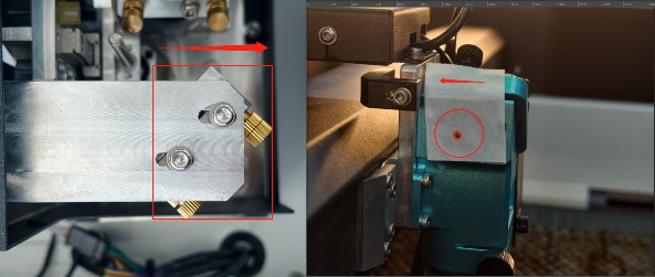 |

7.4.2 Vertical (Y-Axis) Offset
Loosen 4 set bolts on RF Tube Holder. |
|
Important: Use a ruler to ensure the front and Rear knobs are turned equally. |
|
Turn the 2 Knobs Clockwise → Tube Down → Mark Down. |
|
Turn the 2 Knobs CCW → Tube Up → Mark Up. |
|


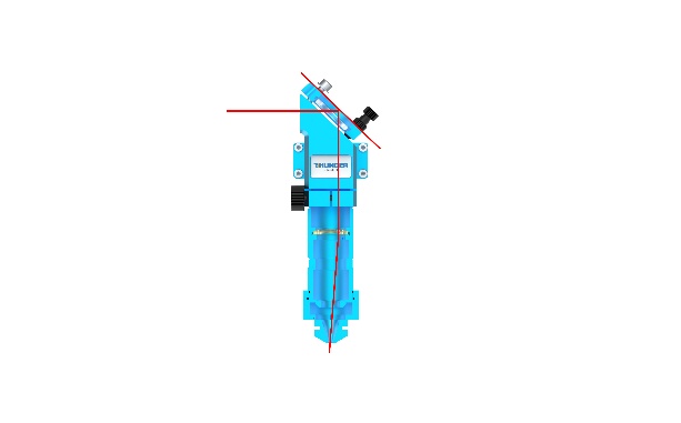
8 PROCEDURE C: VERTICALITY (Z-AXIS)
8.1 Step 1: Nozzle Centering
|
|
|
|
8.1.1 Adjustment (If dots are not centered):
|
|
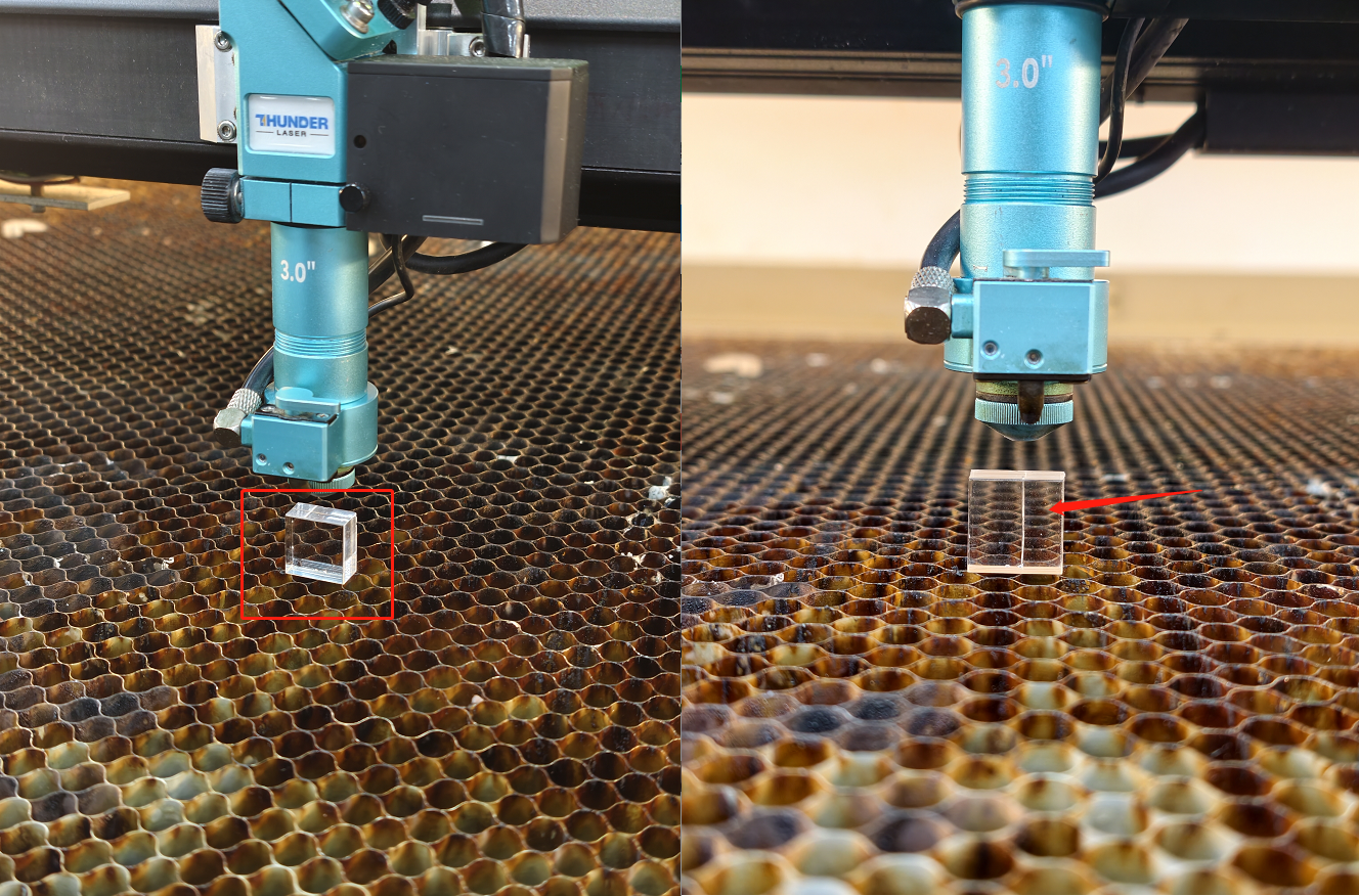
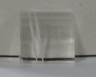
8.2 Step 2: The Acrylic Block Test
|
|
|
|
|
|

8.2.1 Line Profile: /
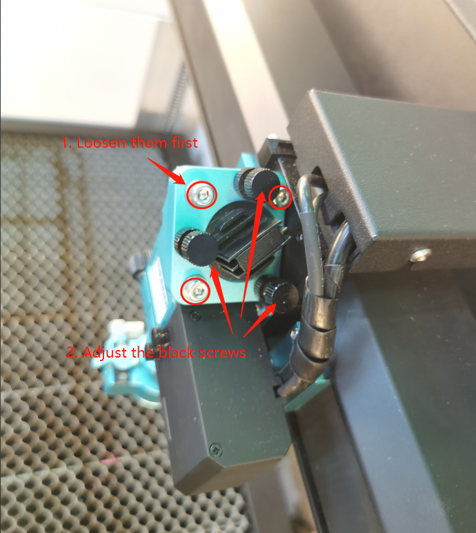
Loosen the 3 silver bolts of the Mirror 3 holder. |
|
⚠️Adjust the black knobs simultaneously, Rotate CCW → Move Holder Downward. |
|
|

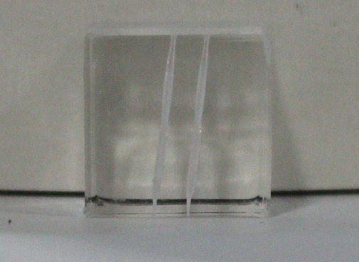
8.2.2 Line Profile: \
Loosen the 3 silver bolts of the Mirror 3 holder. |
|
⚠️Adjust the black knobs simultaneously. Rotate Clockwise → Move Holder Upward. |
|
|
9 PROCEDURE D: RED DOT POINTER
9.1 Step 1: Nozzle / Red Dot Centering
The mirrors are now locked. DO NOT TOUCH MIRRORS.
|  |
| 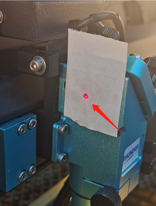 |
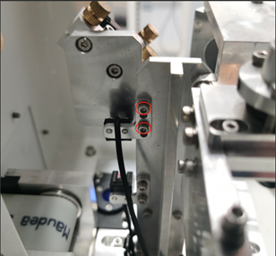
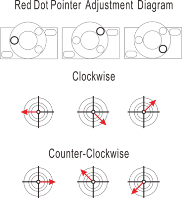
9.1.1 Adjustment (If red dot does not overlap with the burn mark):
Adjust the Red Dot Pointer Holder bolts (rear of the machine) until the red dot and the burn mark overlap. |
 |
10 Support
If you need assistance:
- Open a support ticket with clear photos or videos.
- Refer to: How to Help Tech Support Troubleshoot Faster.
Our support team will assist you as quickly as possible.
Related Articles
Complete Guide to Calibration and Use of TITAN Series Top Camera
Preface Camera calibration ensures precise design alignment for the machine. This guide walks you through the process to boost accuracy and output quality. How to import the calibration file Every machine in the TITAN series has a camera or dual ...Complete Guide to Calibration and Use of TITAN Series Top Camera(New)
Preface Camera calibration ensures precise design alignment for the machine. This guide walks you through the process to boost accuracy and output quality. Please note that the following calibration process is for the new vision algorithm of ...TITAN Series User's Manual
TITAN Series User's Manual Please see attached. Still need help? For specific technical questions or help requests, please open a Ticket with picture or video, so our Support team can assist you ASAP. For the information provided in the ticket, ...Complete Guide to Calibration and Use of TITAN Series Machine CCD
Preface This guide provides clear instructions on how to import calibration files, calibrate the CCD, and use the CCD for the TITAN series machines. By following these steps, you can ensure the proper functioning and accuracy of the camera system. ...Complete Your First Project with Titan PRO
Preface This article focuses on how to complete your first project using the TITAN Pro machine. The operating steps are the same for the TITAN. Connect the Machine to the Software Make sure the machine is connected to LightBurn or LaserMaker. The ...