Titan 51 Dual Laser Source Upgrade Installation Guide
Applicable model: Titan 51-80W with a single CO₂ laser source
Upgrade configuration: CO₂ laser tube + fiber laser source (dual-source system)
Fiber laser options: JPT 60 W or 100 W pulsed fiber laser (select one)
1. Upgrade Overview
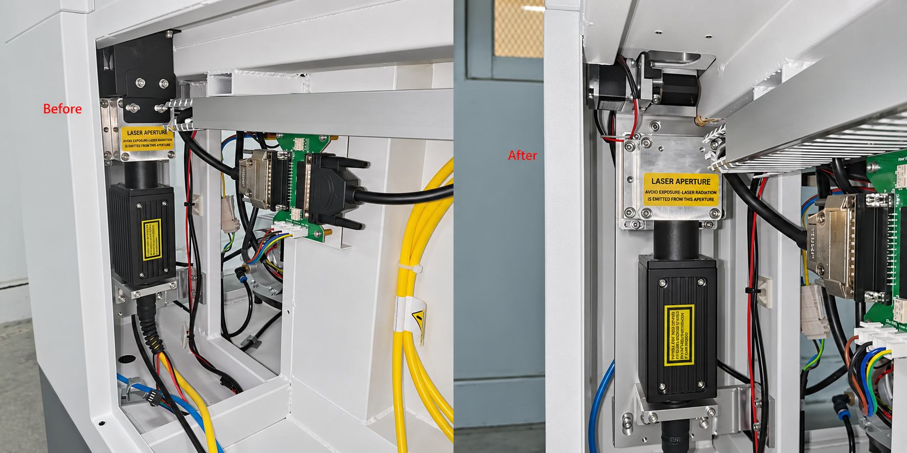
This upgrade adds a fiber laser source and the associated components to the existing Titan 51-80W single-source CO₂ system, enabling switching between the CO₂ and fiber laser sources. No modifications to the internal mechanical structure are required; but component replacement and installation, wiring rearrangement, and laser beam alignment are necessary.
|
Item |
Before Upgrade |
After Upgrade |
|
Laser source type |
CO₂ laser tube (single source) |
CO₂ laser tube + fiber laser source (dual source) |
|
Beam path switching |
None |
Switching module driven by a lead screw stepper motor and linear guide rail |
|
Control system |
Single-source control |
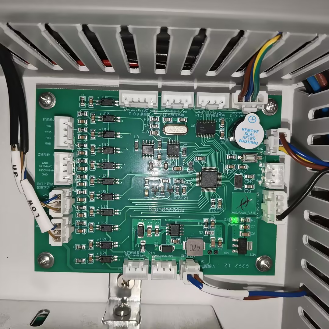
Autofocus_V3.0 control board for dual-source operation |
|
Main enclosure lid |
Lid with single-layer glass |
Double-layer construction (glass + laser safety window), matte blue |
2.Required Components
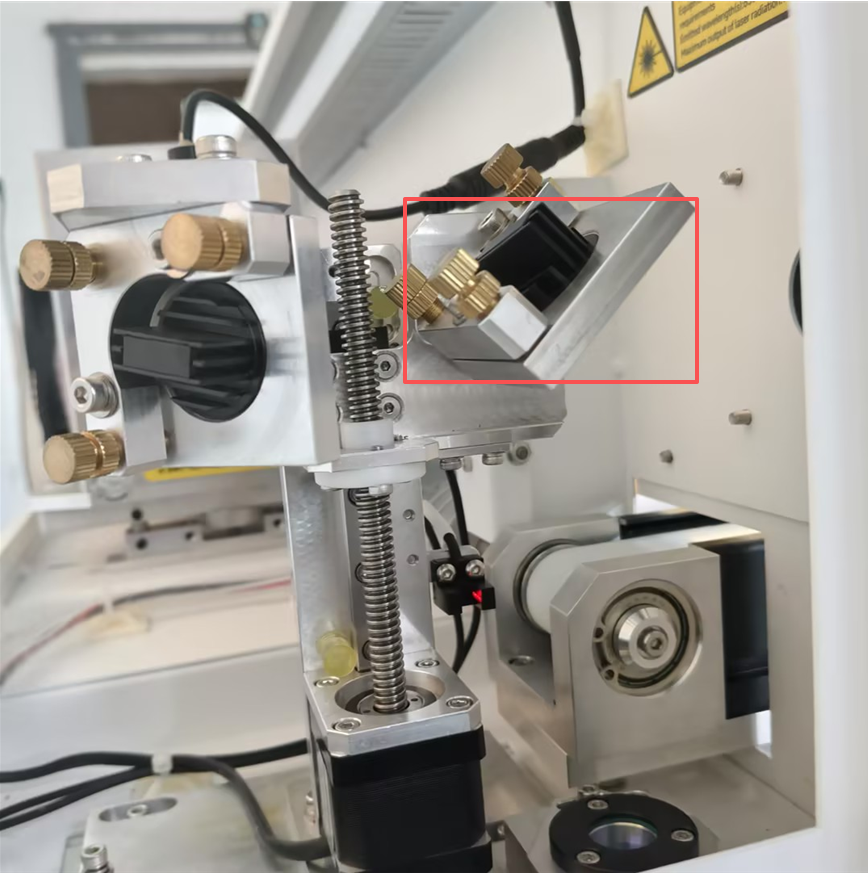
2.1 Dual Laser Source Switching Module
No. | Component | Specs. | Qty. | Image |
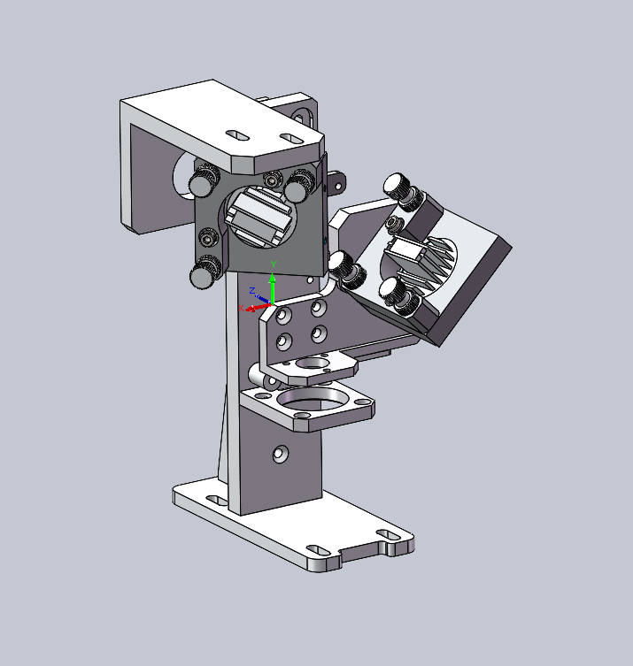
1 | Titan Pro dual-source first mirror module | Titan Pro | 1 set | |
2 | First mirror mount assembly for dual-source switching | LYTE100-0401; AL6061 aluminum, natural finish | 1 set |
|
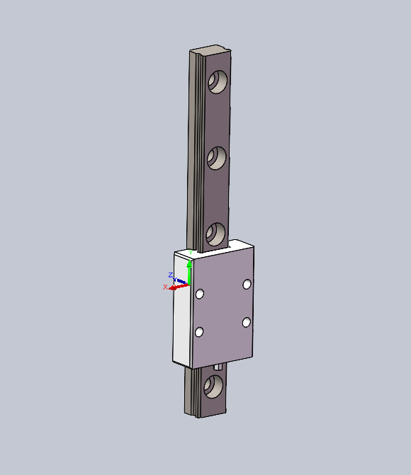
3 | Miniature linear guide rail kit | RN9C-1-95-E10-10 | 1 set |
|
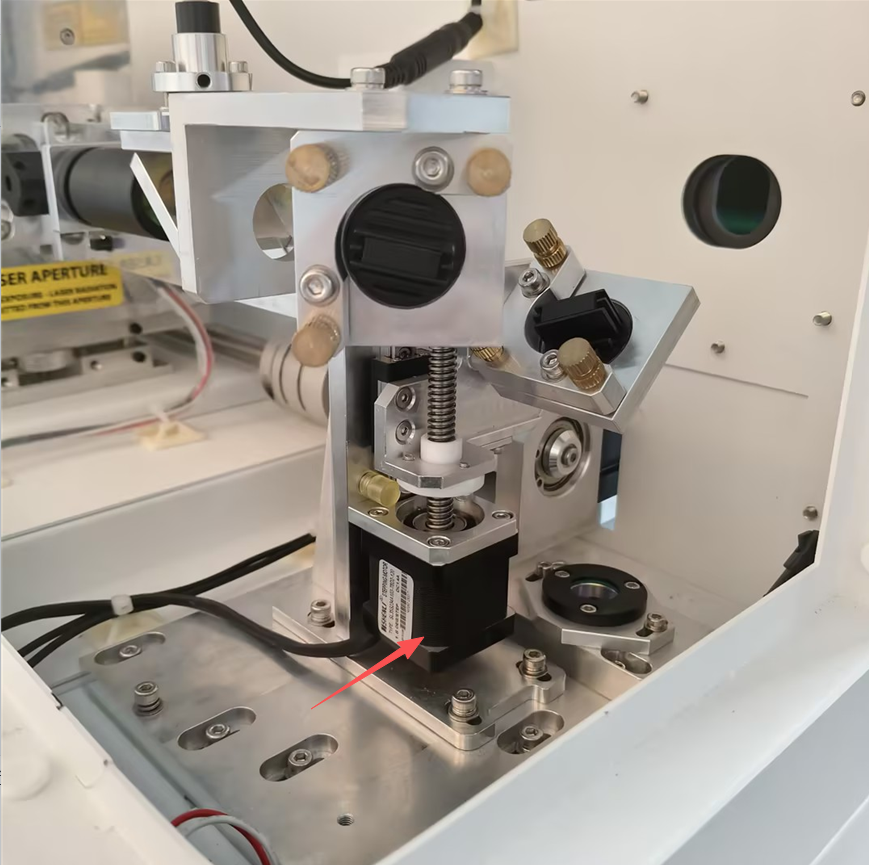
4 | Lead screw stepper motor | SL35S234A103-T8D2-120 | 1 |
|
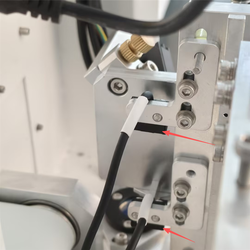
5 | Sensor | SL-205NA-W (ZJF49-L25-H) | 2 |
|
2.2 Fiber Laser Mounting and Adjustment Components
No. | Component | Specs. | Qty. | Image |
6 | Graphene adjustment bracket | LYTE100-0101-019; Q235 steel, matte black | 1 |
|
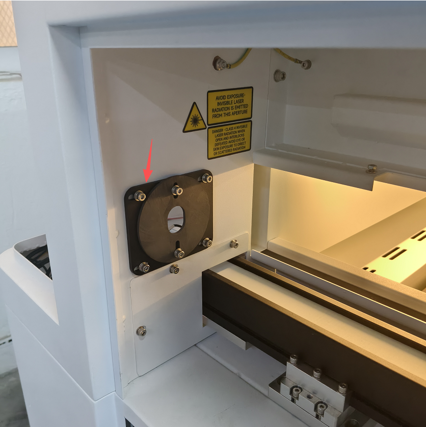
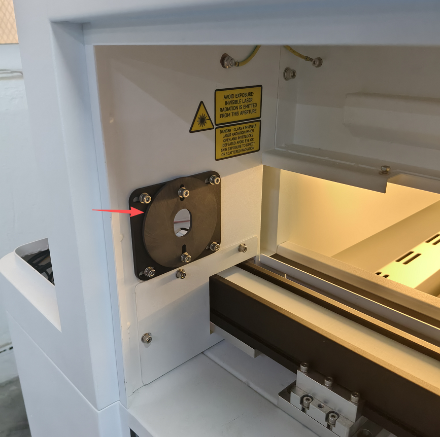
7 | Laser absorber plate | Graphene; Ø80 mm | 1 |
|
Titan fiber laser mounting module | — | 1 set |
| |
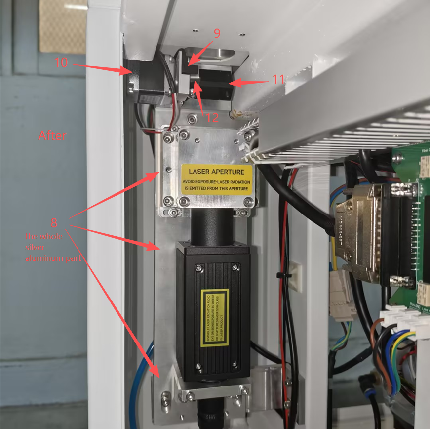
8 | Vertical fiber laser mounting assembly | Titan; AL6061 aluminum, natural finish | 1 set |
|
9 | Sensor | SL-205NA-W (ZJF49-L25-H) | 1 | |
10 | Motor | Self-returning; 40° CCW rotation; R62 | 1 | |
11 | Shutter beam-blocking block A | AL6061 aluminum, ultra-matte black | 1 | |
12 | Actuator Tab A | 304 stainless steel | 1 | |
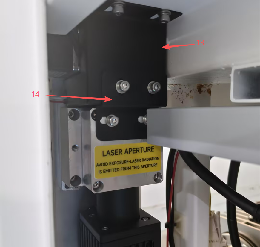
13 | Fiber laser dust cover mounting plate | Titan; Q235 steel, matte black | 1 |
|
14 | Fiber laser dust cover | Q235 steel, matte black | 1 |
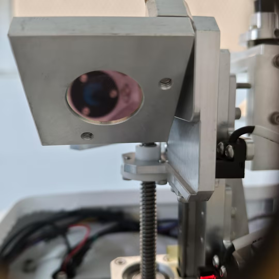
2.3 Optical Components
No. | Component | Specs. | Qty. | Image |
15 | Fiber laser optical window adjustment assembly | Titan; AL6061 aluminum, natural finish | 1 set |
|
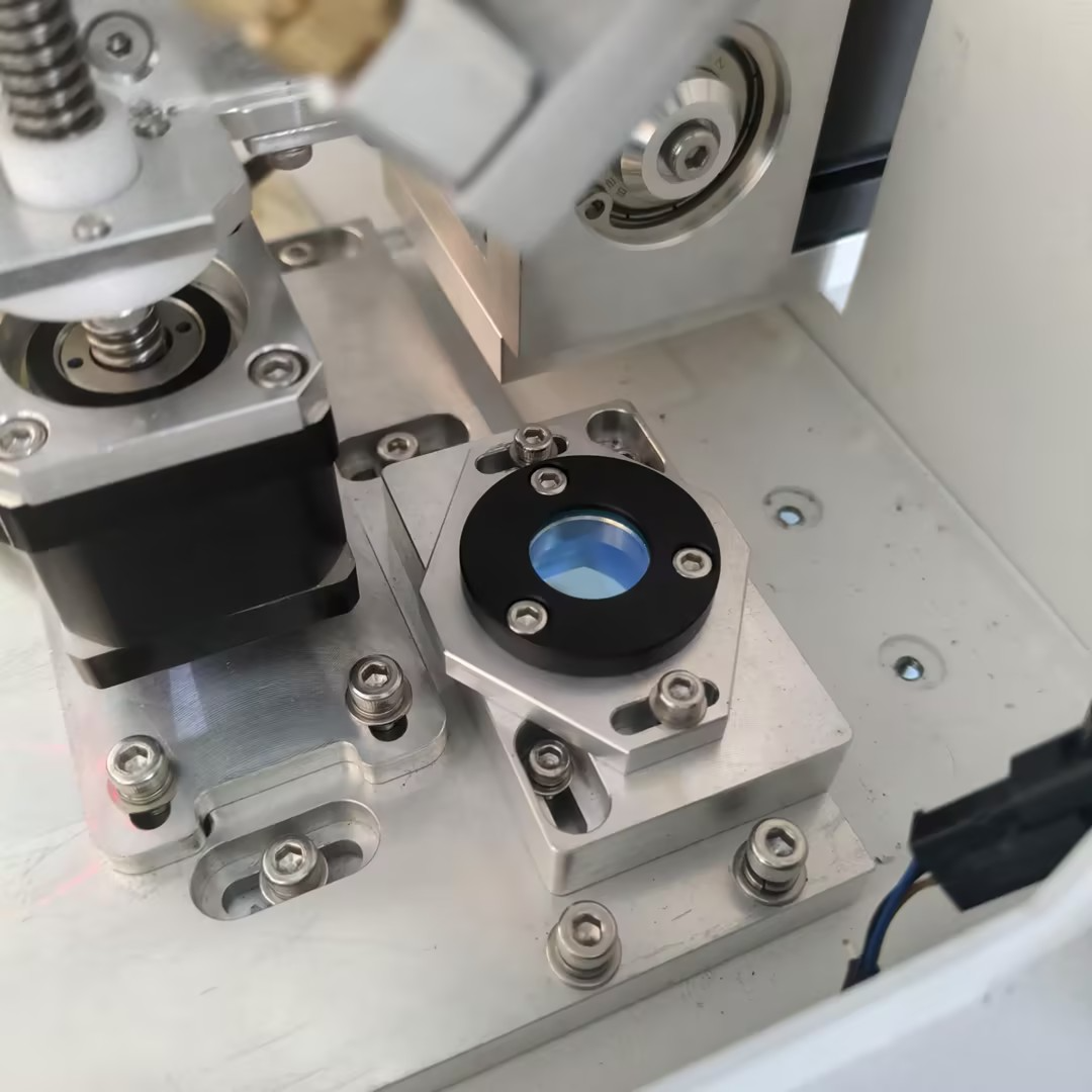
16 | Fiber laser optical window | Ø20 mm × 2 mm thick | 1 | |
17 | Lens O-ring | Green; Ø20 mm; cross-section diameter 1.5 mm | 1 | |
18 | Optical window holder | AL6061 aluminum, matte black; Ø20 mm | 1 | |
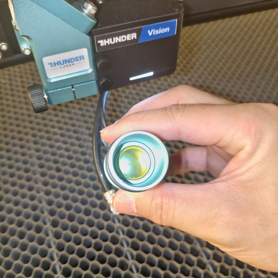
19 | Dual-source focusing lens tube | 3″×Ø20mm | 1 |
|
20 | Dual-source mirror | Ø25 mm | 2 |
|
21 | Fiber laser mirror | Ø25 mm | 1 |
|
22 | Dual-source window | Ø20 mm | 1 |
|
2.4 Protective Covers and Dust Protection Components
No. | Component | Specs. | Qty. | Image | |
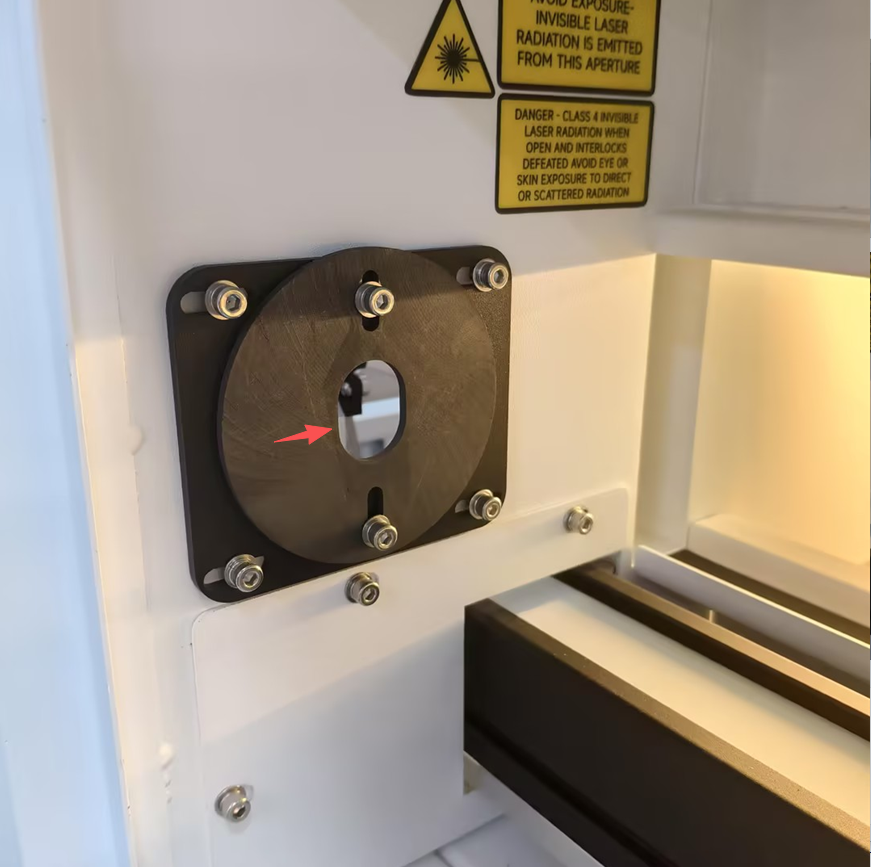
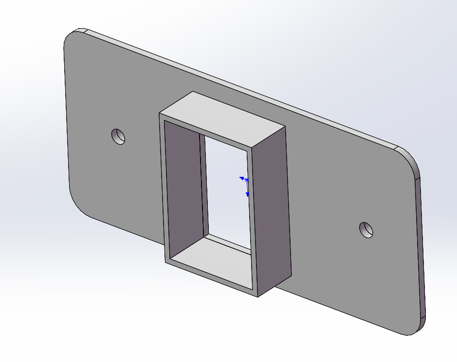
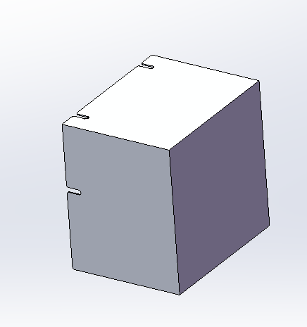
23 | Dual-source first mirror protective cover A | Q235 steel, matte black | 1 |
| |
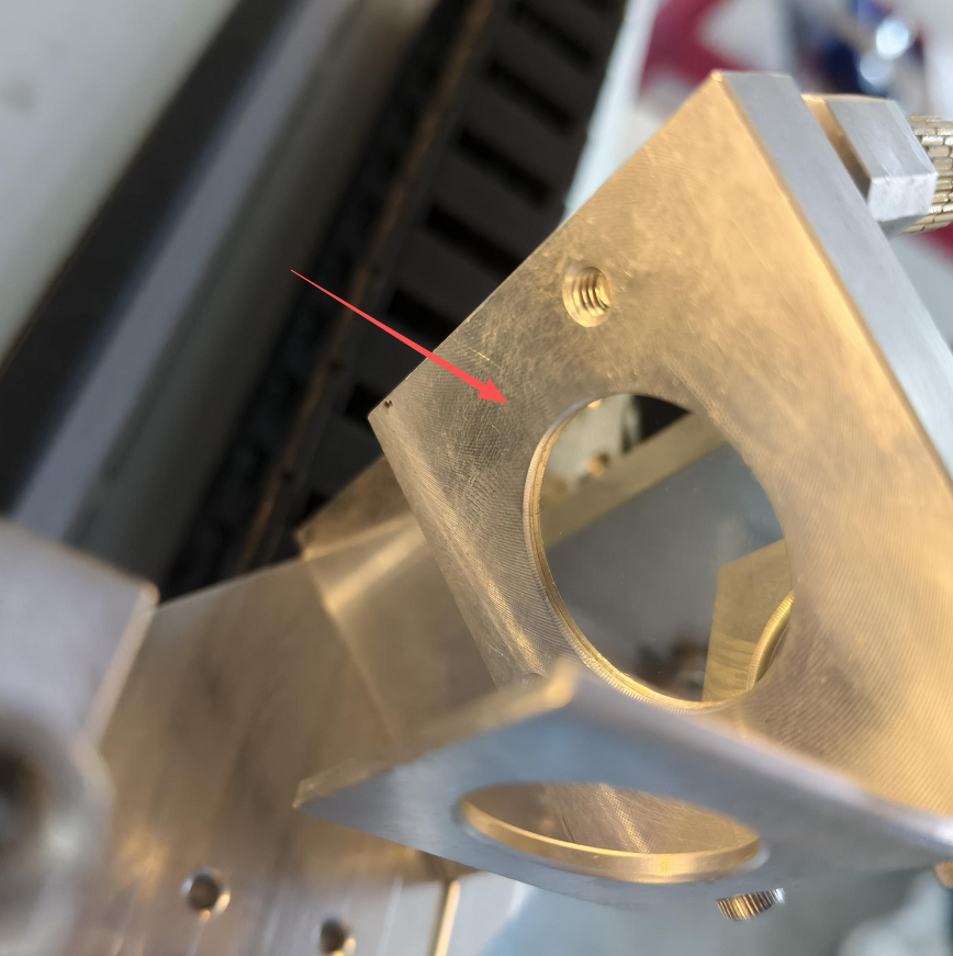
24 | Beam exit adjustment plate for the dual-source first mirror protective cover | Titan, matte black (included in protective cover A) | 1 |
| |
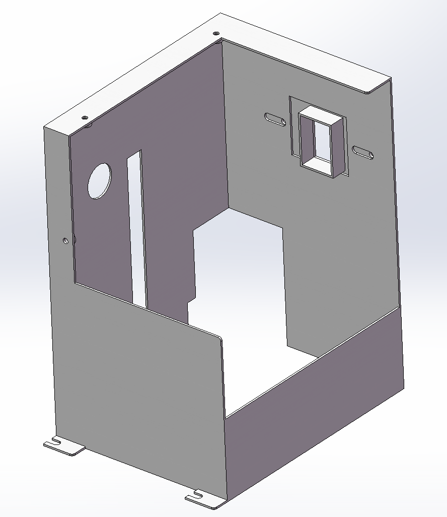
25 | Dual-source first mirror protective cover B | Q235 steel, matte black | 1 |
|
2.5 Enclosure and Acrylic Laser Safety Windows
No. | Component | Specs. | Qty. | Image |
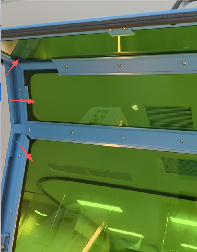
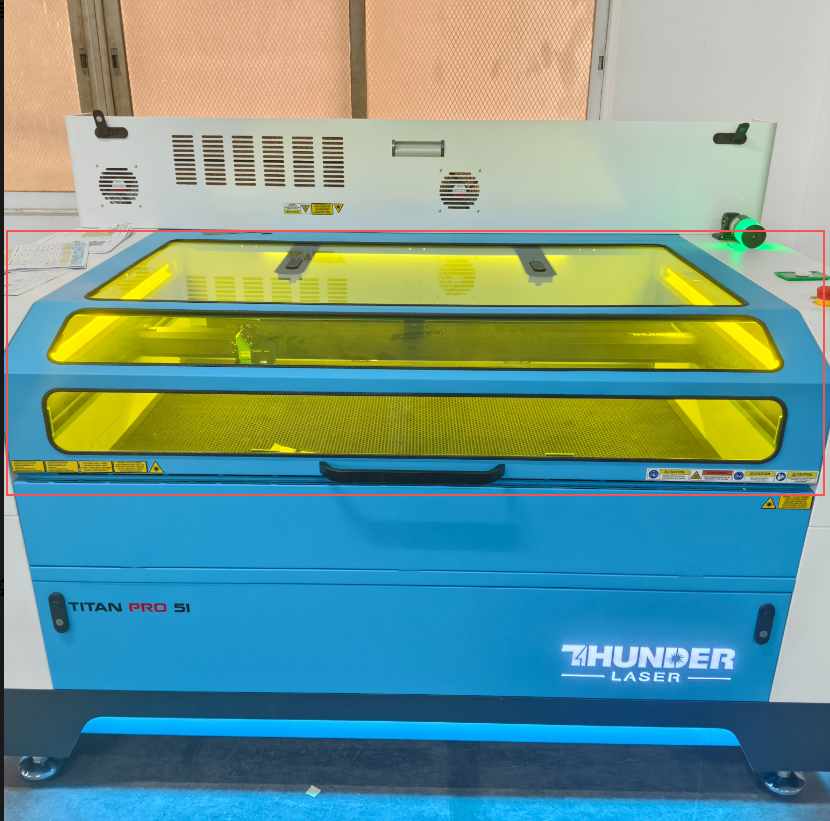
26 | Titan Pro 51 top lid laser safety window | 1290 × 633 mm; 5 mm thick; YLW-6 | 1 |
|
27 | Titan Pro 51 inclined lid laser safety window | 1290 × 162 mm; 5 mm thick; YLW-6 | 1 | |
28 | Titan Pro 51 front lid laser safety window | 1290 × 126 mm; 5 mm thick; YLW-6 | 1 | |
29 | Titan Pro 51_1.0 dual-source main lid | With glass; LYTG100-0105; Q235 carbon steel, matte blue | 1 |
|
30 | Air rods (with mounting hardware) | For the dual-source main lid | 1 set |
2.6 Electrical Control System
No. | Component | Specs. | Qty. | Image |
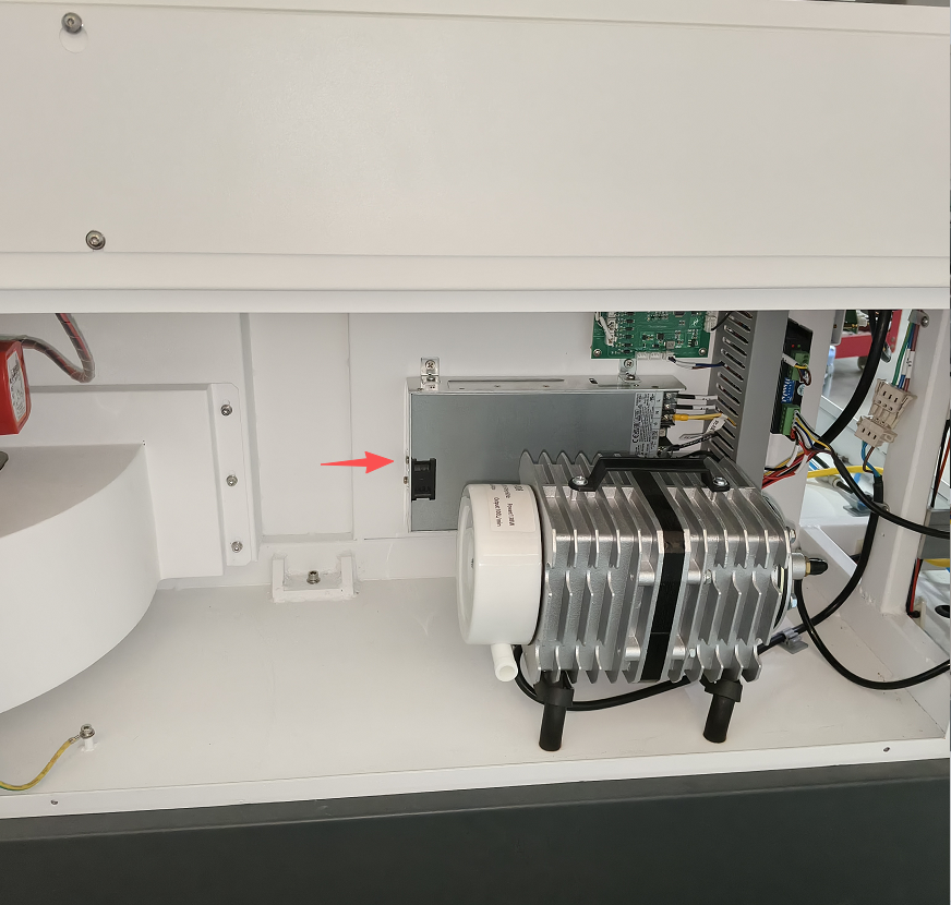
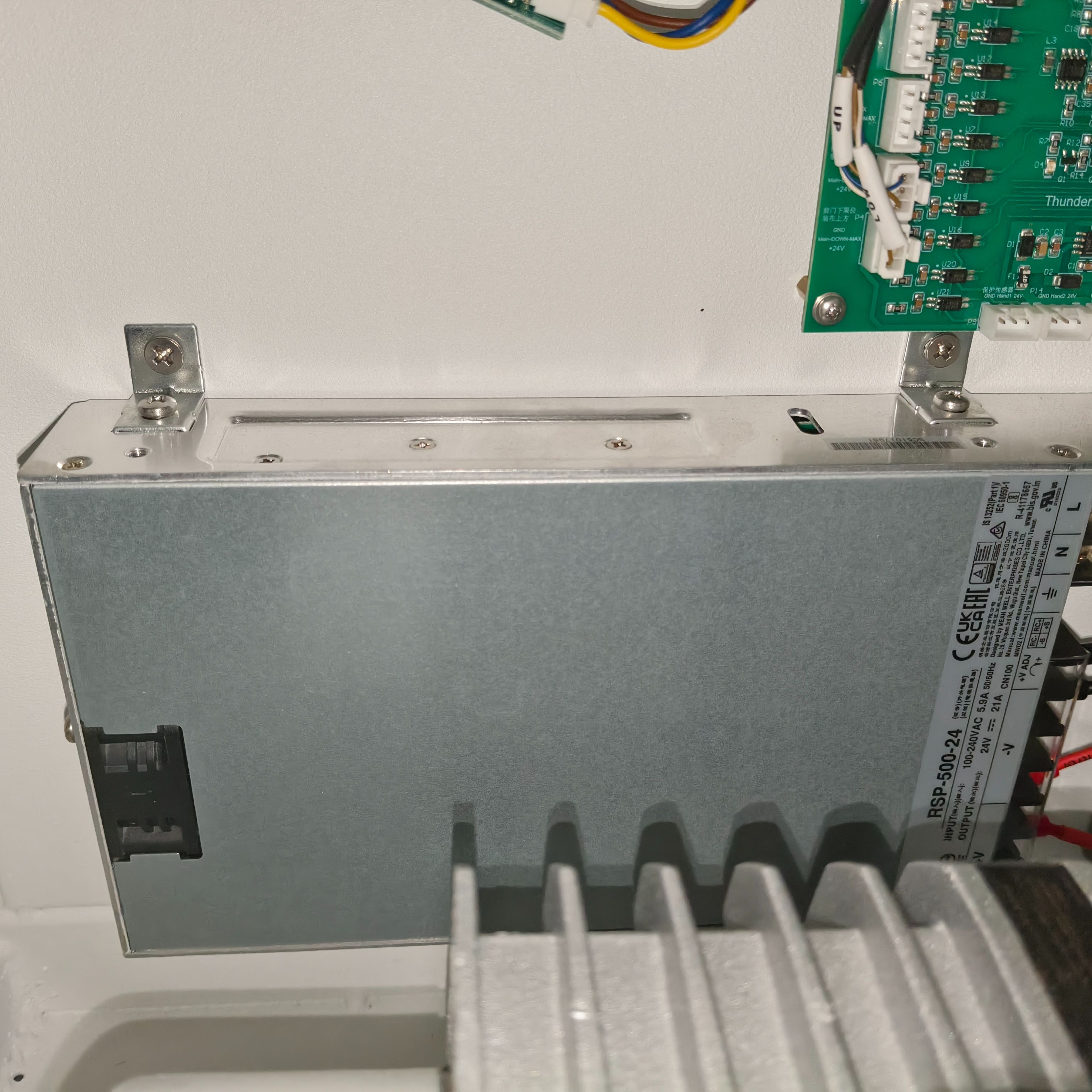
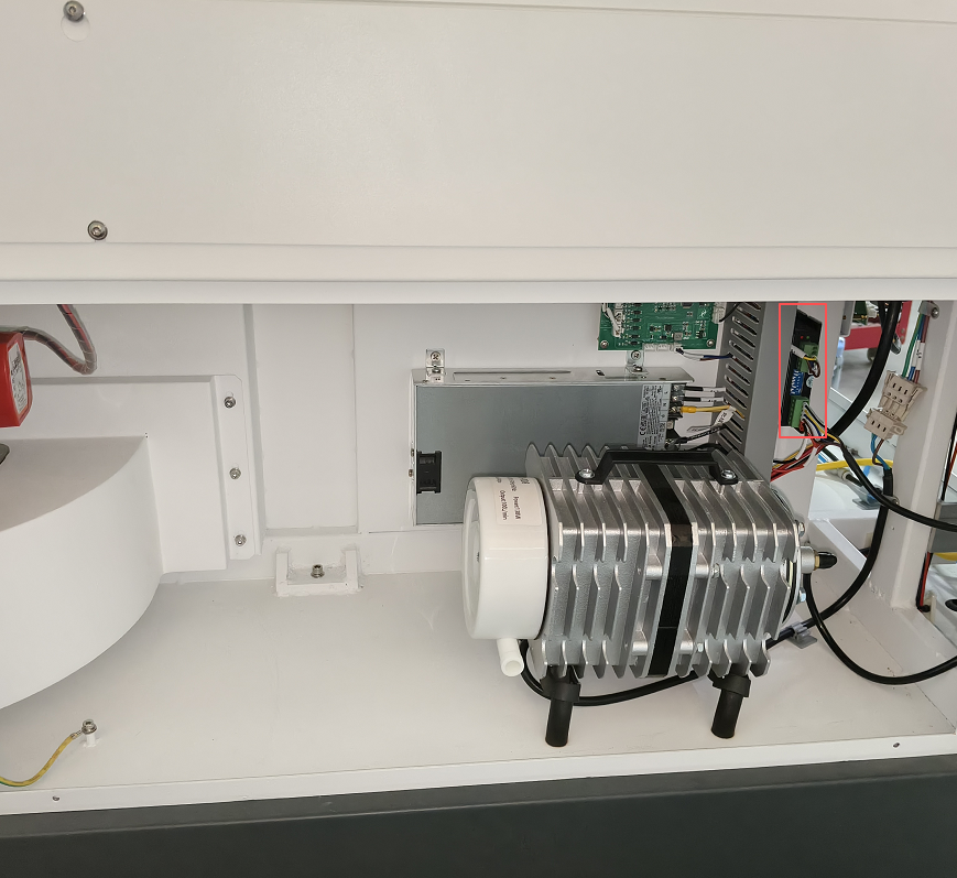
31 | Power supply | RSP-500-24V; with transparent dust cover and MHS012 angle mounting bracket; | 1 |
|
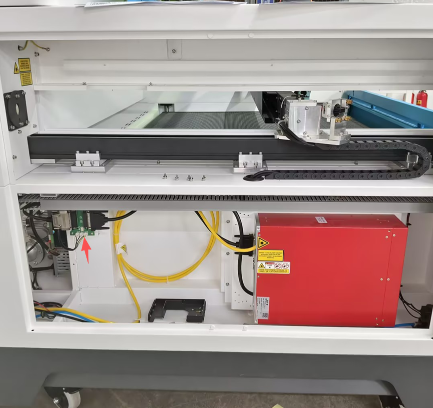
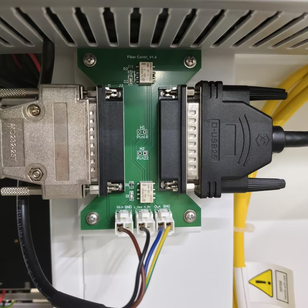
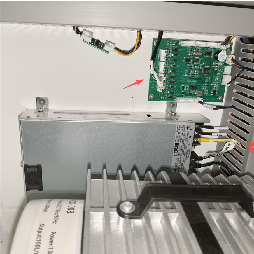
32 | Fiber laser isolation board | Fiber Control V1.4 | 1 |
|
33 | Fiber laser sheet metal mounting bracket | LYTE100-0102-007; Q235 steel, matte white | 1 |
|
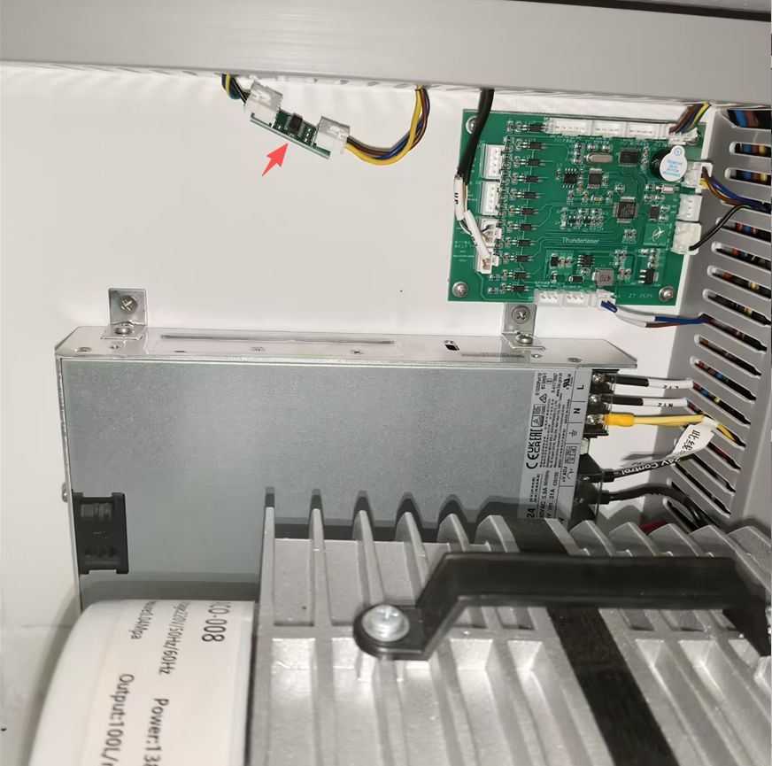
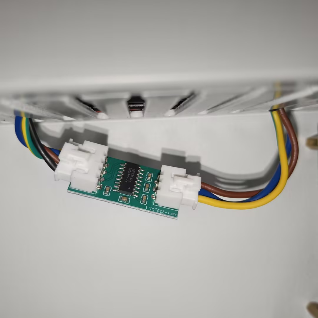
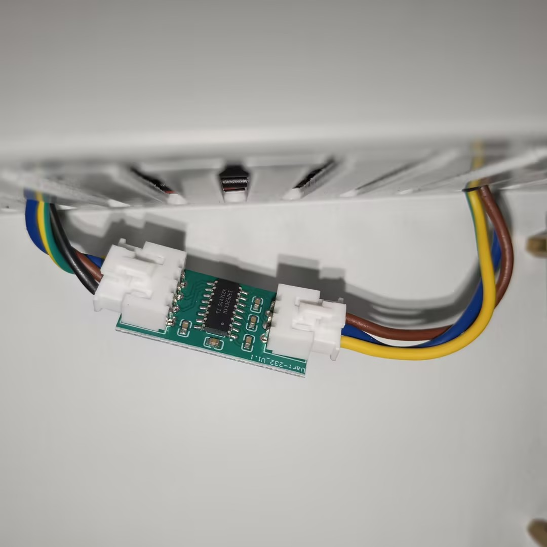
34 | TTL-to-RS232 converter board | V1.0 | 1 |
|
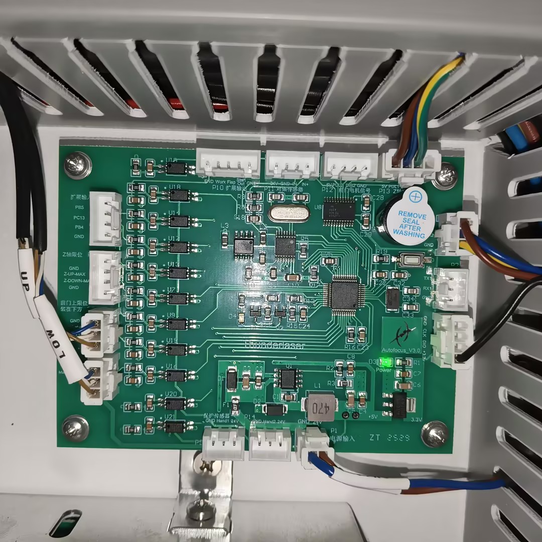
35 | Motor drive control board | Autofocus_V3.0 (for dual-source operation) | 1 |
|
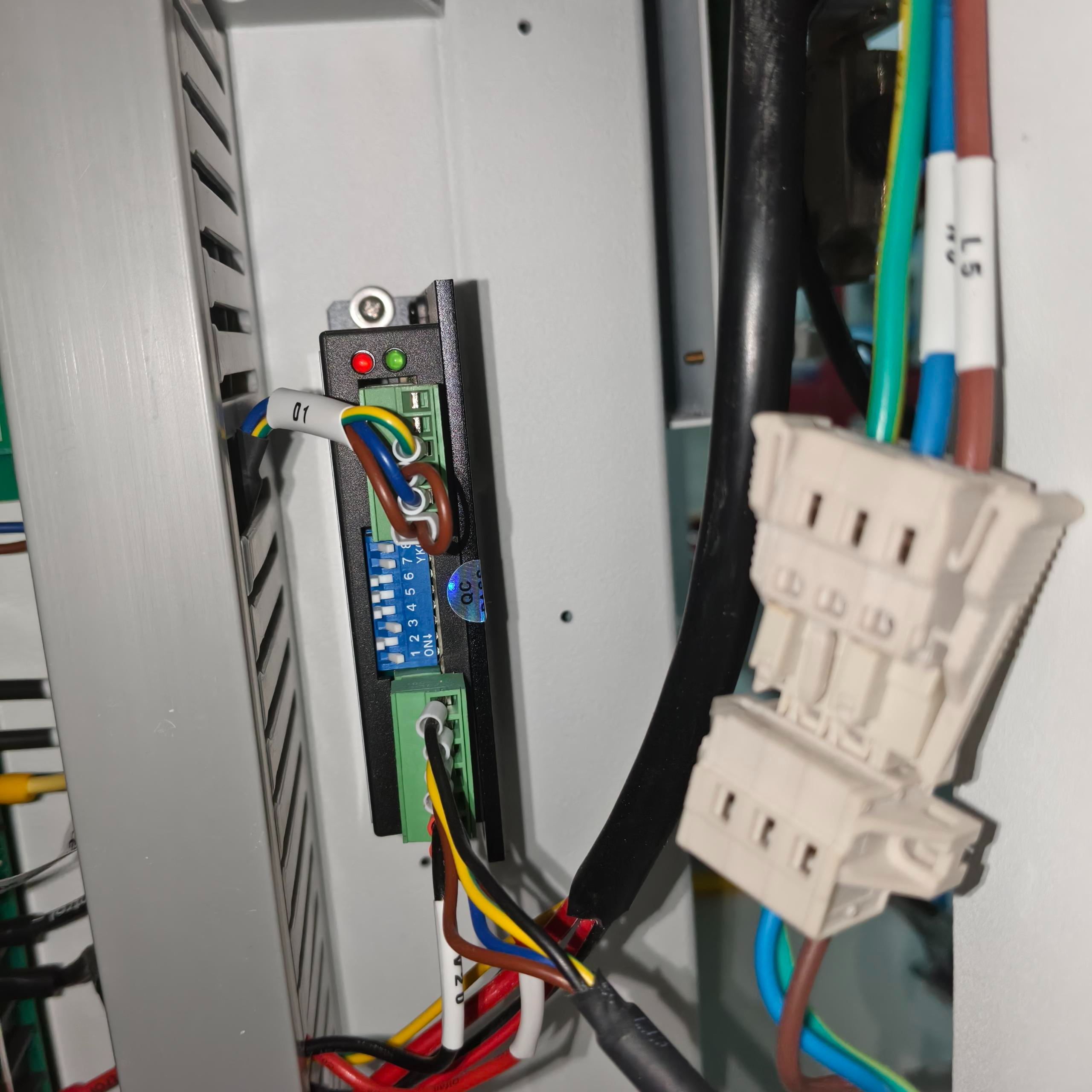
36 | Two-phase stepper motor driver | SL422A | 1 |
 |
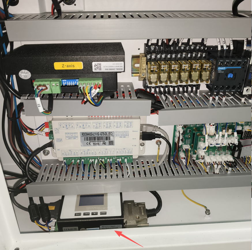
37 | Low-power fiber laser adapter board | RDACC-FIBER-V2; custom black-and-white version | 1 set |
|
2.7 Cables and Connectors
No. | Component | Specs. | Qty. | Image |
38 | DB25 cable | Black, 0.5 m, male-to-female | 1 |
|
39 | DB25 cable | Shielded DB25 cable with metal connector shells, male-to-female, 3 m | 1 |
|
40 | DB25 connector | DB25 male connector; solid pins with gold plating; 45° metal backshell, 2218 | 1 |
|
41 | Serial cable | USB-to-RS232 (male connector, 2 m) | 1 |
|
2.8 Fiber Laser Source Options
No. | Component | Specs. | Qty. | Image |
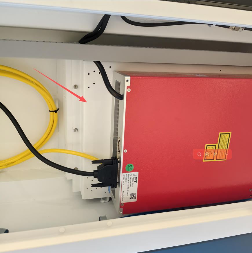
42 | JPT 60 W pulsed fiber laser | YDFLP-E2-60-M7-M-R; 3 m fiber cable | 1 |
|
43 | JPT 100 W pulsed fiber laser | YDFLP-E2-100-M7-M-R (domestic B version); 3 m fiber cable | 1 |
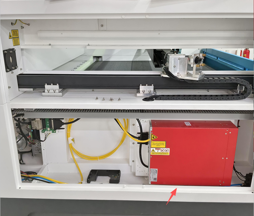
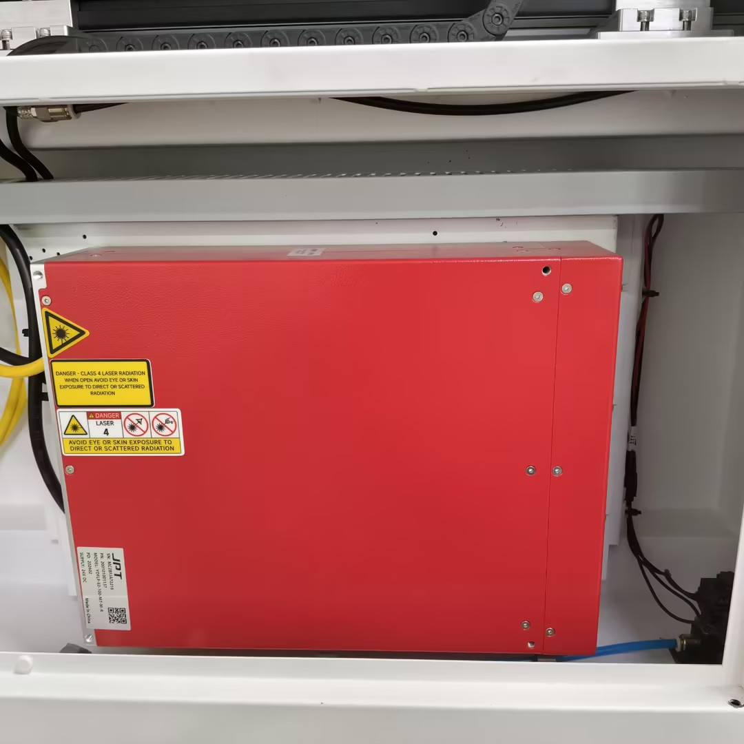
NOTE:Select either Item 42 or Item 43 according to the customer's requirements.
3. Electrical System
The upgrade retains all existing single-source circuits and adds a dual-source switching control circuit.
Existing Single Source Circuits
The single-source electrical system consists of five sections: main power control, control signals, motor drive control, relay control, and door interlock safety circuits.
Additional Dual Source Circuit
With all of the circuits above retained, the following dual-source switching control circuit is added:
Component | Specs. | Qty. | Image | Actual Component |
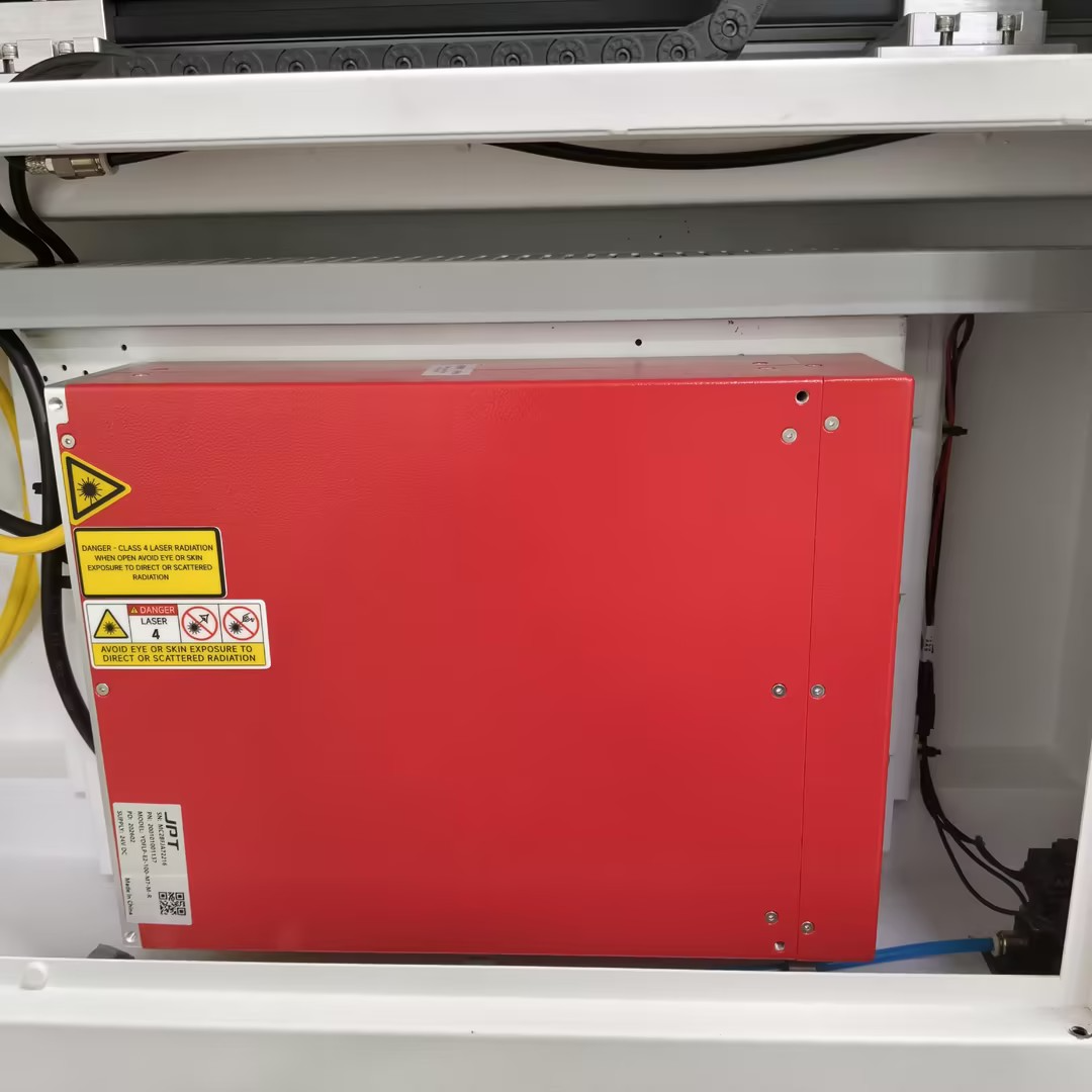
JPT 60 W pulsed fiber laser | YDFLP-E2-60-M7-M-R; 3 m fiber cable | 1 |
| |
JPT 100 W pulsed fiber laser | YDFLP-E2-100-M7-M-R (domestic B version); 3 m fiber cable | 1 | ||
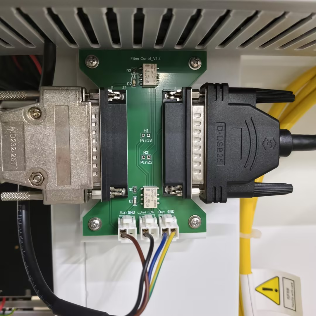
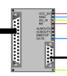
Fiber laser isolation board | Fiber Control V1.4 | 1 |
| |
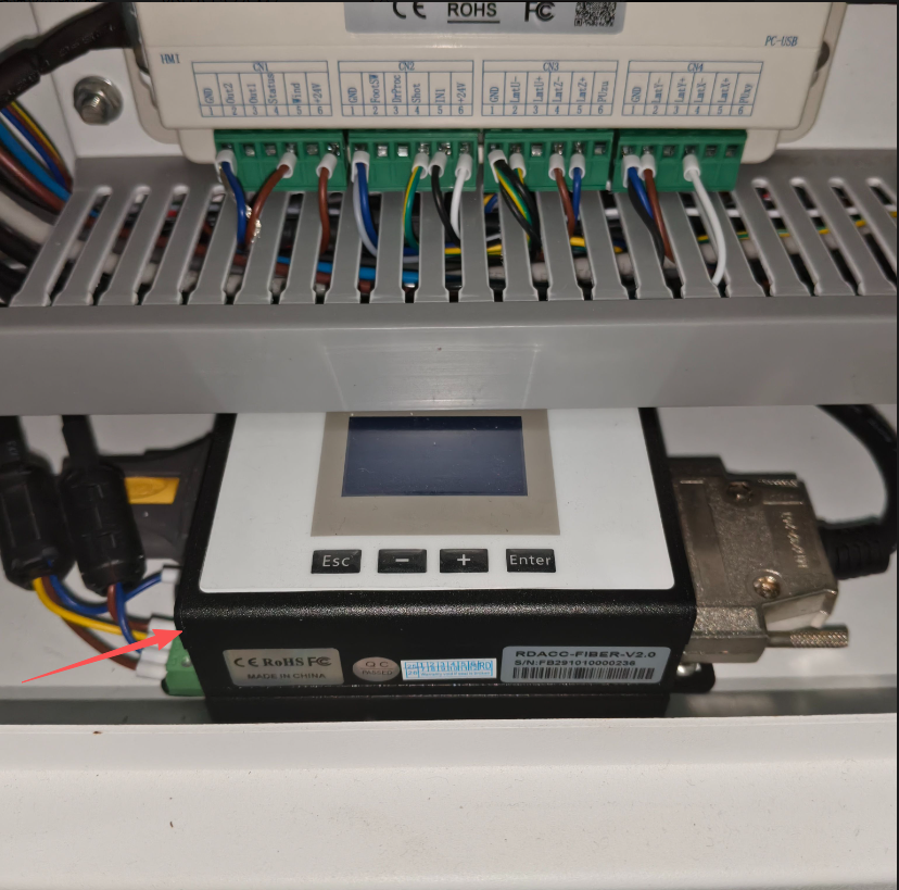
Low-power fiber laser adapter board | RDACC-FIBER-V2; custom black-and-white version | 1 set |
|
|
Switching power supply | RSP-500-24V; with transparent dust cover and MHS012 angle mounting bracket; | 1 | ||
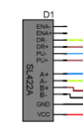
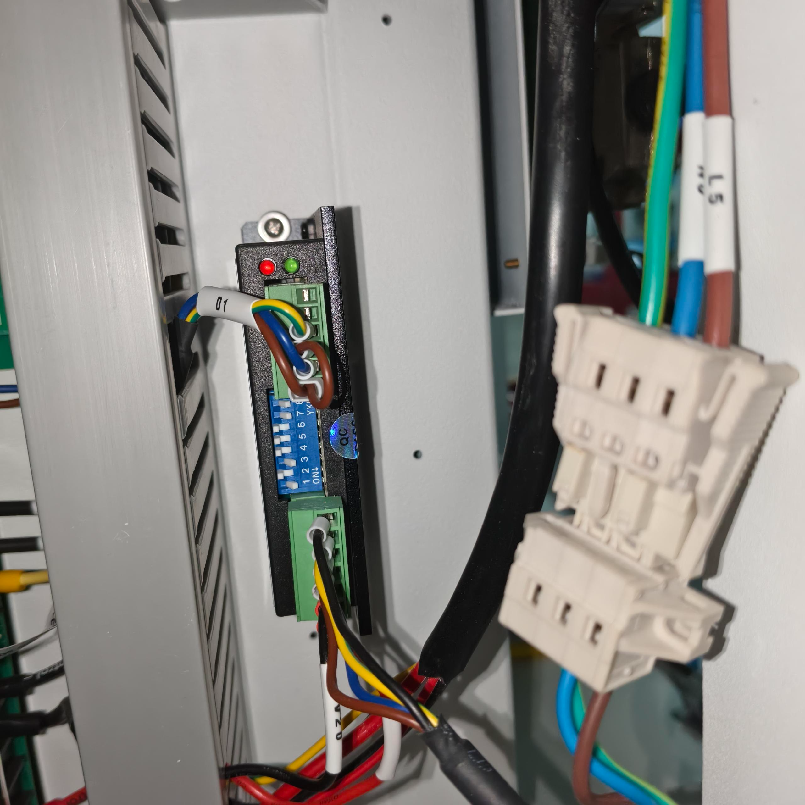
Two-phase stepper motor driver | SL422A | 1 |
|
|
Motor drive control board | Autofocus_V3.0 (for dual-source operation) | 1 |
| |
TTL-to-RS232 converter board | V1.0 | 1 |
|
4. Installation Overview
Step 1 Preparation
Disconnect the machine from the power supply, clear the enclosure, and verify that all components listed in Sections 2.1–2.8 are available.
Step 2 Remove the Existing Components
Remove the existing main lid, air rods, control board, and associated wiring. Label each cable and its connection point before disconnecting it.
Step 3 Install the Beam Path Switching Mechanism
Refer to Section 2.1 Dual Laser Source Switching Module.
Install the miniature linear guide rail kit, lead screw stepper motor, first mirror mount assembly for dual-source switching, and sensors. Install the motor, shutter beam-blocking block A, and Actuator Tab A listed in Section 2.2.
Step 4 Install the Optical Components and Fiber Laser Source
Refer to Section 2.2 Fiber Laser Mounting and Adjustment Components, Section 2.3 Optical Components, and Section 2.8 Fiber Laser Source Options.
Install the dual-source focusing lens, dual-source mirrors, fiber laser mirror, dual-source window, fiber laser optical window, lens O-ring, optical window holder, and fiber laser optical window adjustment assembly.
Install the laser absorber plate, graphene adjustment bracket, fiber laser sheet metal mounting bracket, vertical fiber laser mounting assembly, fiber laser dust cover mounting plate, and fiber laser dust cover. Install and securely fasten the selected JPT 60 W pulsed fiber laser or JPT 100 W pulsed fiber laser.
Step 5 Complete the Electrical Wiring
Refer to Section 2.6 Electrical Control System and Section 2.7 Cables and Connectors.
Install the RSP-500-24V switching power supply and replace the existing control board with the Autofocus_V3.0 motor drive control board for dual-source operation.
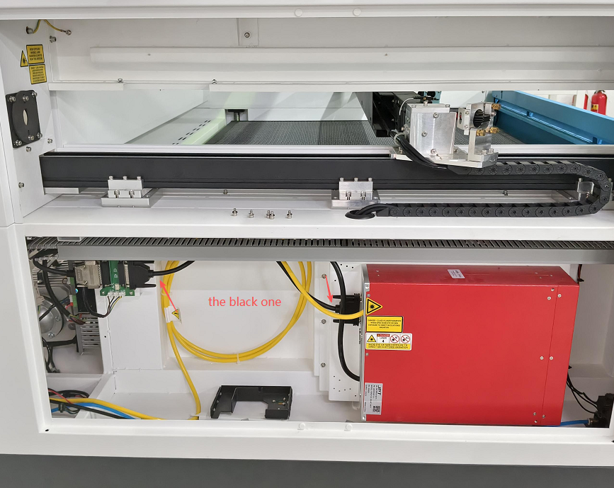
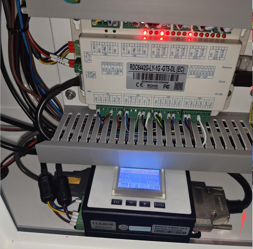
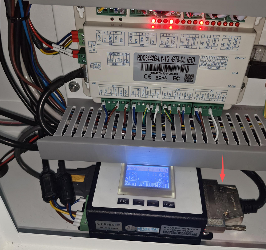
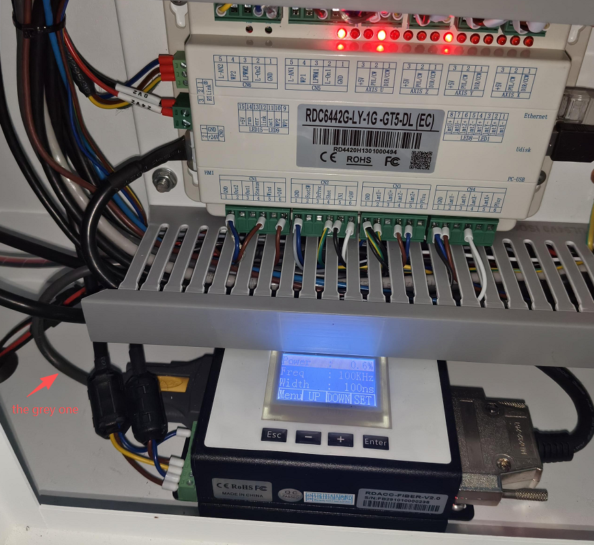
Install and connect the SL422A two-phase stepper motor driver, Fiber Control V1.4 fiber laser isolation board, TTL-to-RS232 converter board, and RDACC-FIBER-V2 low-power fiber laser adapter board. Complete the connections to the installed fiber laser source using the 0.5 m and 3 m DB25 cables, DB25 connector, and USB-to-RS232 serial cable, following the wiring diagram.
Step 6 Install the New Enclosure Components
Refer to Section 2.4 Protective Covers and Dust Protection Components and Section 2.5 Enclosure and Acrylic Laser Safety Windows.
Install the Titan Pro 51_1.0 dual-source main lid (matte blue) and the following three laser safety windows:
- Titan Pro 51 top lid laser safety window
- Titan Pro 51 inclined lid laser safety window
- Titan Pro 51 front lid laser safety window
Install the dual-source first mirror protective cover A, including its beam exit adjustment plate, and dual-source first mirror protective cover B. Install the new air rods with their mounting hardware.
Step 7 Power On and Test
Verify that all components are securely installed and all wiring connections are correct before applying power. Power on the machine and test CO₂ laser emission, fiber laser emission, and switching between the two sources. Reconfigure the device parameters in LightBurn and test each laser source separately.
5. Precautions
1. The fiber laser is a Class 4 laser product. Always wear laser safety eyewear specifically intended for the laser when operating it.
2. Align the beam path after installing the optical components.
3. Ensure that the newly installed RSP-500-24V power supply is properly grounded.
4. Reconfigure the device parameters in LightBurn after the upgrad