How to Use Roller Rotary on Your Machine
Preface
This guide provides step-by-step instructions for setting up and operating the roller rotary attachment, which is compatible with all Thunder Laser models. The configuration shown uses the Thunder Bolt as an example. It covers basic installation and parameter configuration to help you achieve consistent, high-quality results when processing cylindrical objects.
1. Parts Overview
Check Item | PIC |
| |
|
2. Parts Instruction
Before we begin, let's review the functions of each adjustment knob on the rotary attachment.
Function Intro | Operation Guide | Reference Image |
| Turn the knob counterclockwise to tighten the belt and clockwise to loosen it. | |
| ||
Flip it to the unlocked position to slide the unit freely along the rail for position adjustment. | ||
| To level the workpiece (such as a tapered cup), turn the adjustment knob counterclockwise to raise the corresponding module/foot and clockwise to lower it. | |
Note: Before making any height adjustments, first release the lock on this lever. Secure the lever again once you have finished adjusting the height. | ||
| When working with longer workpieces, you can reposition this screw along the slot to extend the maximum supported length on the right side. | |
Note: The maximum extension length is 6mm. |
3. Specific steps
3.1. Installation & Wiring
Step Content | Operation Instruction | Reference Image |
| First, lower the worktable to a safe height. Then, place the rotary attachment on the machine's worktable, aligning it parallel to the X-axis. | |
If the workpiece to be processed is too large and exceeds the Z-axis travel range, you can remove the honeycomb table and use the tray to complete the processing. Rotary trays are available (optionally) for Bolt and Bolt Plus 24 as of May 2026. Note: Please place the tray according to the direction indicated by the arrow. | ||
| The minimum workpiece diameter for processing is 40mm. For the Thunder Bolt series:
| |
| Clamp the workpiece first, then loosen the adjustment knobs on both sides and adjust the rollers up/down until the workpiece is level and centered. | |
| Plug the rotary cable into the dedicated rotary axis port on the machine. Tighten the connector to ensure a stable connection. |
3.2. Software Configuration
This case includes installation and operation instructions for three different software options supported by the system.
Users are not required to install or use all three software programs. Depending on your workflow, operating preferences, licensing conditions, or existing software environment, you may choose the software that best suits your needs.
Please refer only to the sections relevant to the software you intend to use.
Software
Setup Instruction
Reference Image
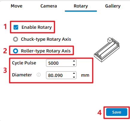
LaserMaker Settings
- Go to the "Rotary" tab.
- Check Enable Rotary.
- Select "Roller-type Rotary Axis".
- Set Cycle Pulse (5000).
- Enter the workpiece Diameter (mm).
- Click "Save".
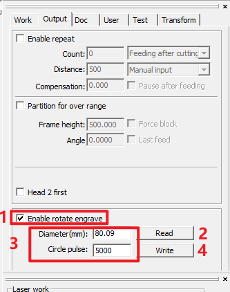
RDWorks Settings
- Go to the "Output" tab.
- Check Enable rotate engrave.
- Click "Read" to read the settings.
- Enter the workpiece Diameter (mm).
- Set Circle pulse (5000).
- Click "Write" to save the settings.
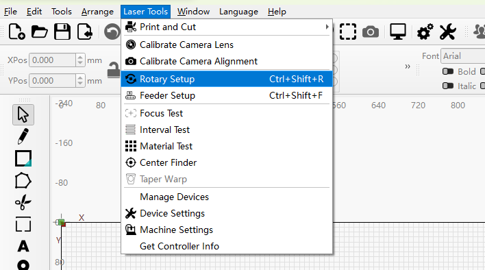
LightBurn Settings
- Go to the Laser Tools menu → select Rotary Setup.
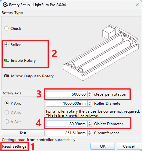
- Click "Read Settings" (bottom-left corner) to retrieve existing parameters from the controller.
- In the Rotary Type section:
- Select "Roller" as the rotary type.
- Check Enable Rotary to activate the function.
- Configure key parameters:
- Steps per rotation: Enter the motor steps (5000).
- Object Diameter: Input the actual diameter of the workpiece(mm).
- Click "OK" to save the settings.
This case includes installation and operation instructions for three different software options supported by the system.
Users are not required to install or use all three software programs. Depending on your workflow, operating preferences, licensing conditions, or existing software environment, you may choose the software that best suits your needs.
Please refer only to the sections relevant to the software you intend to use.
Software | Setup Instruction | Reference Image |
LaserMaker Settings |
| |
RDWorks Settings |
| |
LightBurn Settings |
|
3.3. Test Run & Operation
The following operation steps will be illustrated using LaserMaker as an example.
Step Content | Operation Instruction |
| |
| |
| |
|
💡 Pro Tip:
To avoid material damage or waste caused by incorrect settings, we recommend a low-power test run before full engraving.
- Cover the cup surface with masking tape or paper.
- Reduce the laser power to a minimum.
- Run the full job to verify the design orientation, size, and rotary axis parameters. Once confirmed, remove the protective layer and proceed with the formal engraving at your normal settings.
Still need help?
For specific technical questions or help requests, please open a Ticket with picture or video, so our Support team can assist you ASAP.
For the information provided in the ticket, please refer to this link:
Help Tech Support Troubleshoot Faster
End.
Related Articles
How to use the chuck rotary for Aurora Series
Please click the link below for the details How to use the Rotary with an AURORA 8 - YouTube Internal and External Jaws of Fiber Rotary (youtube.com) Chuck Rotary Usage Instructions of THUNDER LASER AURORA Fiber Marking Machine (youtube.com) End.Complete Guide to Calibration and Use of TITAN Series Machine CCD
Preface This guide provides clear instructions on how to import calibration files, calibrate the CCD, and use the CCD for the TITAN series machines. By following these steps, you can ensure the proper functioning and accuracy of the camera system. ...Aurora & Bolt Series Chuck Rotary
Chuck Rotary Dimensions Default Dip Switch Settings 1 ON (Steps bit 1) 2 OFF (Steps bit 2) 3 ON (Steps bit 3) 4 OFF (Steps bit 4) 5 OFF (CW\CWW) 6 OFF (Test Mode) Dip Switch Settings and Steps Table Default Steps Default Motor Steps is 4000. Due to ...Rotary axis attachment has a wrong cylindrical engraving/cutting size
Problem description: The engraving/cutting size is incorrect when you using the rotary attachment. Reasons: 1. Wrong circle pulse or diameter (1) Circle pulse Check the gear ratio on your rotary attachment. Gear ratio 4:1 structure, like below. ...The machine won't turn on
Reasons: 1. Emergency Stop key is pressed Solution: If it’s pressed, please reset it, like below. 2. The circuit breaker has tripped Locate on the lower right-hand door panel (or back side door panel). Solution: Please check if it’s in off position, ...